
Technical Specs
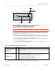
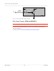
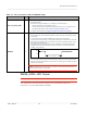
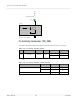
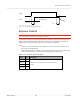
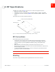
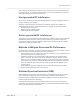
Table Of Contents
- Important Notice
- Safety and Hazards
- Limitation of Liability
- Contents
- List of Tables
- List of Figures
- 1: Introduction
- 2: Electrical Specifications
- 3: RF Specifications
- 4: Power
- 5: Software Interface
- 6: Mechanical and Environmental Specifica- tions
- 7: Regulatory Compliance and Industry Certifi- cations
- A: Antenna Specification
- B: Design Checklist
- C: Testing
- AT Command Entry Timing Requirement
- Acceptance Testing
- Certification Testing
- Production Testing
- Functional Production Test
- Quality Assurance Testing
- Suggested Testing Equipment
- Testing Assistance Provided by Lantronix, Inc.
- IOT/Operator Testing
- Extended AT Commands for Testing
- D: Packaging
- E: References
- F: Acronyms

Rev 5 May.21
35
41113694
Electrical
Specifications
TX_ON
V_APT
* V_APT – Internal power sou rce for RF PA
Figure 2-10: TX_ON State During Transmission
Antenna Control
Note: Host support for antenna control signals is optional.
The EM7411 provides four output signals (listed in Table 2-10) that may be used for host
designs that incorporate tunable antennas. Customers can configure these signals as
appropriate for the operating band(s) using the command AT!ANTSEL.
Note:
•
Lantronix, Inc. recommends that two signals be used for high bands, and the other
two signals for low/mid bands.
•
To avoid detuning the PCC band, customers must make sure there are no GPIO state
conflicts between the PCC and SCC for all supported CA combinations.
Table 2-10: Antenna Control Signals
Name Pin Description
ANTCTL0 59
Customer-defined external switch controls for tunable
antennas
ANTCTL1 61
ANTCTL2 63
ANTCTL3 65
Voltage Drop
T
advance
T
de
lay