
Technical Specs
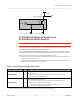
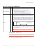
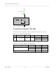
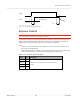
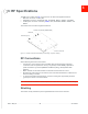
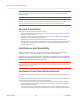
Table Of Contents
- Important Notice
- Safety and Hazards
- Limitation of Liability
- Contents
- List of Tables
- List of Figures
- 1: Introduction
- 2: Electrical Specifications
- 3: RF Specifications
- 4: Power
- 5: Software Interface
- 6: Mechanical and Environmental Specifica- tions
- 7: Regulatory Compliance and Industry Certifi- cations
- A: Antenna Specification
- B: Design Checklist
- C: Testing
- AT Command Entry Timing Requirement
- Acceptance Testing
- Certification Testing
- Production Testing
- Functional Production Test
- Quality Assurance Testing
- Suggested Testing Equipment
- Testing Assistance Provided by Lantronix, Inc.
- IOT/Operator Testing
- Extended AT Commands for Testing
- D: Packaging
- E: References
- F: Acronyms

Rev 5 May.21
34
41113694
Product
Technical
Specification
VCC
Figure 2-9: Example LED
Tx Activity Indicator (TX_ON)
The module provides a digital output signal to indicate the occurrence of Tx activity.
Table 2-8: Tx Activity Indicator States
Pin Signal name
Direction
a
I/O type Module state Signal State
61
TX_ON
Output
1.8V
During Tx activity High
No Tx Low
a. Signal direction with respect to module—TX_ON (pin 5) is an output from the module to the
host.
Table 2-9: Tx Activity Indicator Characteristics
Parameter
Min Max
T
advance
LTE 89 µs —
UMTS 46 µs —
T
delay
— 699 ms
Current limiting Resistor
LED
Module
LED#
MIO