
Technical Specs
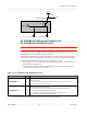
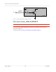
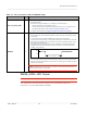
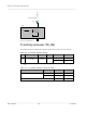
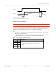
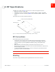
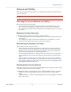
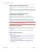
Table Of Contents
- Important Notice
- Safety and Hazards
- Limitation of Liability
- Contents
- List of Tables
- List of Figures
- 1: Introduction
- 2: Electrical Specifications
- 3: RF Specifications
- 4: Power
- 5: Software Interface
- 6: Mechanical and Environmental Specifica- tions
- 7: Regulatory Compliance and Industry Certifi- cations
- A: Antenna Specification
- B: Design Checklist
- C: Testing
- AT Command Entry Timing Requirement
- Acceptance Testing
- Certification Testing
- Production Testing
- Functional Production Test
- Quality Assurance Testing
- Suggested Testing Equipment
- Testing Assistance Provided by Lantronix, Inc.
- IOT/Operator Testing
- Extended AT Commands for Testing
- D: Packaging
- E: References
- F: Acronyms

Rev 5 May.21
33
41113694
Electrical
Specifications
Table 2-7:
Full_Card_Power_Off# and RESET# Usage
Name Pin Description / notes
Full_Card_Power_Off#
6
Powers the module on/off.
•
Signal is required.
•
Pull HIGH to keep the module on. To keep the module always on:
·
Tie the pin directly to a host GPIO (1.8V), or
·
Use an external pull-up to pull signal high (10–20k for 1.8V, 75–100k for VCC
rail). Note that a larger-value resistor will reduce leakage current.
•
To power off the module, see Required Shutdown Sequence on page 51.
RESET#
67
Resets the module.
•
Signal is optional. The module will operate correctly if the pin is left disconnected
on the host.
•
To reset the module, pulse the RESET# pin with a logic low signal for
3 (min) to 5.5 seconds (max)— if the signal is held low for more than 5.5 seconds,
the reset cycle restarts, and if it continues to be held low through several cycles,
the module will not fully boot.
Otherwise, leave the signal floating or high impedance (the module will remain
operational because the module has a pull-up resistor to an internal reference
voltage (1.8V) in place.).
RESET#
High
Low
3–5.5 sec
•
The signal requires an open collector input from the host.
•
This is a ‘hard’ reset, which should be used only if the host cannot communicate
with the module via the USB port. (If the port is not working, the module may have
locked up or crashed.)
Caution: RESET# should not be driven or pulled to a logic high level by the host, as
this may cause damage to the module.
WWAN_LED#— LED
Output
Note: Host support for WWAN_LED# is optional.
The configuration for the LED shown in Figure 2-9 is customizable. Contact your
Lantronix, Inc. account representative for details.