
Technical Specs
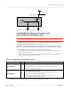
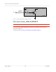
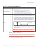
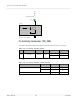
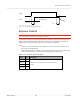
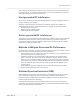
Table Of Contents
- Important Notice
- Safety and Hazards
- Limitation of Liability
- Contents
- List of Tables
- List of Figures
- 1: Introduction
- 2: Electrical Specifications
- 3: RF Specifications
- 4: Power
- 5: Software Interface
- 6: Mechanical and Environmental Specifica- tions
- 7: Regulatory Compliance and Industry Certifi- cations
- A: Antenna Specification
- B: Design Checklist
- C: Testing
- AT Command Entry Timing Requirement
- Acceptance Testing
- Certification Testing
- Production Testing
- Functional Production Test
- Quality Assurance Testing
- Suggested Testing Equipment
- Testing Assistance Provided by Lantronix, Inc.
- IOT/Operator Testing
- Extended AT Commands for Testing
- D: Packaging
- E: References
- F: Acronyms

Rev 5 May.21
31
41113694
Electrical
Specifications
VCC
Host
Figure 2-7: Recommended WAKE_ON_WAN# Connection
W_DISABLE1# (Wireless Disable) and
W_DISABLE2# (GNSS Disable)
Note: Host support for wireless/ GNSS disable signals is optional.
The host device uses W_DISABLE1# to enable/ disable the WWAN or radio modem, and
W_DISABLE2# to enable/disable GNSS functionality.
Letting these signals float high allows the module to operate normally. These pins have
100 kΩ pull-up resistors. See Figure 2-8 on page 32 for a recommended implementation.
When integrating with your host device, keep the following in mind:
•
The signal is an input to the module and should be driven LOW to turn the radio off, or
HIGH or floating to keep it on.
•
If the host never needs to assert this power state control to the module, leave this
signal unconnected from the host interface.
Table 2-6: W_DISABLE1# / W_DISABLE2# Usage
Name Pin Description / notes
W_DISABLE1#
8
Enable/disable the WWAN or radio modem
a
. When disabled, the modem cannot
transmit or receive.
•
Leave as not connected or drive HIGH to keep the modem always on.
•
Drive LOW to turn the modem off.
W_DISABLE2#
26
Enable/disable GNSS functionality
a
•
Leave as not connected or drive HIGH to enable GNSS functionality.
•
Drive LOW to disable GNSS functionality.
•
For details on enabling / disabling GNSS functionality, see the
AT!CUSTOM=”GPSENABLE” command
.
a. Lantronix, Inc. recommends that the host implement an open collector driver where a Low signal turns off the modem or dis-
ables GNSS functionality, and a high signal turns on the modem or enables GNSS functionality.
5k-100k
WAKE_ON_WAN#
3
1
Q
Control
R
2
Module