
Technical Specs
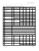
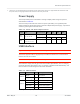
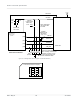
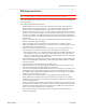
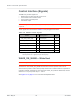
Table Of Contents
- Important Notice
- Safety and Hazards
- Limitation of Liability
- Contents
- List of Tables
- List of Figures
- 1: Introduction
- 2: Electrical Specifications
- 3: RF Specifications
- 4: Power
- 5: Software Interface
- 6: Mechanical and Environmental Specifica- tions
- 7: Regulatory Compliance and Industry Certifi- cations
- A: Antenna Specification
- B: Design Checklist
- C: Testing
- AT Command Entry Timing Requirement
- Acceptance Testing
- Certification Testing
- Production Testing
- Functional Production Test
- Quality Assurance Testing
- Suggested Testing Equipment
- Testing Assistance Provided by Lantronix, Inc.
- IOT/Operator Testing
- Extended AT Commands for Testing
- D: Packaging
- E: References
- F: Acronyms

Rev 5 May.21
30
41113694
Product
Technical
Specification
Control Interface (Signals)
The EM7411 provides signals for:
•
Waking the host when specific events occur
•
Host control of the module’s radios
•
Host control of module power
•
LED driver output
Note: Host support for Full_Card_Power_Off# is required, and support for other signals in Table 2-5
is optional.
These signals are summarized in Table 2-5 and paragraphs that follow.
Table 2-5:
Module Control Signals
Name Pin Description
Type
a
Full_Card_Power_Off# 6 On/off signal PD
W_DISABLE1# 8 Wireless disable (Main RF) PU
WWAN_LED# 10 LED driver OC
WAKE_ON_WAN# 23 Wake host O
W_DISABLE2# 26 Wireless disable (GNSS) PU
RESET# 67 Reset module PU
a. O—Digital pin Output; OC—Open Collector output; PD— Digital pin Input,
internal pull down; PU—Digital pin Input, internal pull up
WAKE_ON_WAN# — Wake Host
Note: Host support for WAKE_ON_WAN# is optional.
The EM7411 uses WAKE_ON_WAN# to wake the host when specific events occur.
The host must provide a 5 kΩ–100 kΩ pullup resistor that considers total line capacitance
(including parasitic capacitance) such that when
WAKE_ON_WAN# is deasserted, the line
will rise to 3.7 V (Host power rail) in < 100 ns.
See Figure 2-7 on page 31 for a recommended implementation.