
Technical Specs
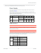
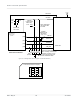
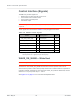
Table Of Contents
- Important Notice
- Safety and Hazards
- Limitation of Liability
- Contents
- List of Tables
- List of Figures
- 1: Introduction
- 2: Electrical Specifications
- 3: RF Specifications
- 4: Power
- 5: Software Interface
- 6: Mechanical and Environmental Specifica- tions
- 7: Regulatory Compliance and Industry Certifi- cations
- A: Antenna Specification
- B: Design Checklist
- C: Testing
- AT Command Entry Timing Requirement
- Acceptance Testing
- Certification Testing
- Production Testing
- Functional Production Test
- Quality Assurance Testing
- Suggested Testing Equipment
- Testing Assistance Provided by Lantronix, Inc.
- IOT/Operator Testing
- Extended AT Commands for Testing
- D: Packaging
- E: References
- F: Acronyms

Rev 5 May.21
28
41113694
Contact View (notched corner at top left)
Product
Technical
Specification
Figure 2-5: SIM Application Interface (applies to both SIM interfaces)
RFU
C8
C4
RFU
I/O
C7
C3
CLK
VPP
C6
C2 RST
GND
C5
C1
VCC
Figure 2-6: SIM Card Contacts (Contact View)
SIM Detect
UIM-PWR
4.7uF
X5R
typ
0.1uF
(Optional.
Locate
near the
SIM socket)
15 kΩ - 30 kΩ
Located near
SIM socket
UIM-DATA
UIM-RESET
SIM card connector
ESD
protection
Located near SIM socket.
NOTE:
Carefully consider if
ESD
protection is required
– it may
increase signal rise time and
lead to certification failure
UIM_GND
(C7)
(C2)
(C5)
(C1)
(C3)
(C9)
Note: SIM Detect
contact may vary
by vendor
UIM-CLK
(Optional.
Locate
near the
SIM socket)
47 pF, 51 Ω
NOTE: UIM signals
refer to both UIM1
and UIM2.
EM7411