
Technical Specs
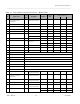
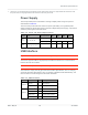
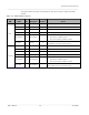
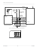
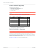
Table Of Contents
- Important Notice
- Safety and Hazards
- Limitation of Liability
- Contents
- List of Tables
- List of Figures
- 1: Introduction
- 2: Electrical Specifications
- 3: RF Specifications
- 4: Power
- 5: Software Interface
- 6: Mechanical and Environmental Specifica- tions
- 7: Regulatory Compliance and Industry Certifi- cations
- A: Antenna Specification
- B: Design Checklist
- C: Testing
- AT Command Entry Timing Requirement
- Acceptance Testing
- Certification Testing
- Production Testing
- Functional Production Test
- Quality Assurance Testing
- Suggested Testing Equipment
- Testing Assistance Provided by Lantronix, Inc.
- IOT/Operator Testing
- Extended AT Commands for Testing
- D: Packaging
- E: References
- F: Acronyms

Rev 5 May.21
27
41113694
Electrical
Specifications
The types of SIM connectors used depends on how the host device exposes the SIM
sockets.
Table 2-4:
SIM Interface Signals
SIM
Name
Pin
Description
SIM
contact
a
Notes
Primary
UIM1_RESET 30 Reset 2 Active low SIM reset
UIM1_CLK 32 Serial clock 3 Serial clock for SIM data
UIM1_DATA 34 Data I/O 7 Bi-directional SIM data line
UIM1_PWR 36 SIM voltage 1 Power supply for SIM
SIM_DETECT
66
SIM indication
-
Input from host indicating whether SIM is present or not
•
Grounded if no SIM is present
•
No-connect (floating) if SIM is inserted
UIM_GND
Ground
5
Ground reference
UIM_GND is common to module ground
Secondary
UIM2_RESET 46 Reset 2 Active low SIM reset
UIM2_CLK 44 Serial clock 3 Serial clock for SIM data
UIM2_DATA 42 Data I/O 7 Bi-directional SIM data line
UIM2_PWR 48 SIM voltage 1 Power supply for SIM
SIM_DETECT_2
40
SIM indication
-
Input from host indicating whether SIM is present or not
•
Grounded if no SIM is present
•
No-connect (floating) if SIM is inserted
UIM2_GND
SIM indication -
Ground reference
UIM2_GND is common to module ground
a.
See Figure 2-6 on page 28 for SIM card contacts.