
Technical Specs
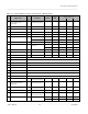
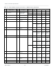
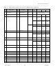
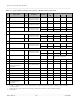
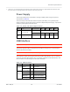
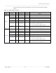
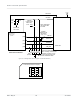
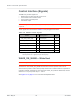
Table Of Contents
- Important Notice
- Safety and Hazards
- Limitation of Liability
- Contents
- List of Tables
- List of Figures
- 1: Introduction
- 2: Electrical Specifications
- 3: RF Specifications
- 4: Power
- 5: Software Interface
- 6: Mechanical and Environmental Specifica- tions
- 7: Regulatory Compliance and Industry Certifi- cations
- A: Antenna Specification
- B: Design Checklist
- C: Testing
- AT Command Entry Timing Requirement
- Acceptance Testing
- Certification Testing
- Production Testing
- Functional Production Test
- Quality Assurance Testing
- Suggested Testing Equipment
- Testing Assistance Provided by Lantronix, Inc.
- IOT/Operator Testing
- Extended AT Commands for Testing
- D: Packaging
- E: References
- F: Acronyms

Rev 5 May.21
21
41113694
Electrical
Specifications
Table 2-1:
Host Interface (75-pin) Connections — Module View
a
Pin
Signal name
Pin
type
b
Description
Direction
c
Active
state
Voltage levels (V)
Min Typ Max
1
CONFIG_3
(NC in default module
configuration)
Reserved—Host must
not repurpose this pin.
2
VCC
V
Power source Input Power 3.135 3.7 4.4
3
GND
V
Ground Input Power
- 0 -
4
VCC
V
Power source Input Power 3.135 3.7 4.4
5
GND
V
Ground Input Power
- 0 -
6
Full_Card_Power_Off#
d
PD Turn module on Input High 0.7
-
4.4
Turn module off Input Low
-
0.3
-
0.5
7
USB_D+
d
-
USB data positive Input/Output Differential
- - -
8
W_DISABLE1#
e
PU Wireless Disable (main
RF radio)
Input Low
- -
0.4
Input High 0.7
-
4.4
9
USB_D-
d
-
USB data negative Input/Output Differential
- - -
10 WWAN_LED# OC LED Driver Output Low
0 -
0.15
11 GND
V
Ground Input Power
- 0 -
12 Key Notch location
13 Key Notch location
14 Key Notch location
15 Key Notch location
16 Key Notch location
17 Key Notch location
18 Key Notch location
19 Key Notch location
20 NC
Reserved—Host must
not repurpose this pin.
21
CONFIG_0
(GND in default module
configuration)
Reserved—Host must
not repurpose this pin.
Output
-
0
22 NC
Reserved—Host must
not repurpose this pin.
23 WAKE_ON_WAN#
d
OC Wake Host Output Low
0
0.1
24 NC
Reserved—Host must
not repurpose this pin.
25 DPR
-
Dynamic power control Input High 1.17 1.80 2.10
Input Low
-
0.3
-
0.63