
Technical Specs
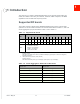

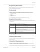
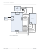
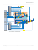
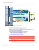
Table Of Contents
- Important Notice
- Safety and Hazards
- Limitation of Liability
- Contents
- List of Tables
- List of Figures
- 1: Introduction
- 2: Electrical Specifications
- 3: RF Specifications
- 4: Power
- 5: Software Interface
- 6: Mechanical and Environmental Specifica- tions
- 7: Regulatory Compliance and Industry Certifi- cations
- A: Antenna Specification
- B: Design Checklist
- C: Testing
- AT Command Entry Timing Requirement
- Acceptance Testing
- Certification Testing
- Production Testing
- Functional Production Test
- Quality Assurance Testing
- Suggested Testing Equipment
- Testing Assistance Provided by Lantronix, Inc.
- IOT/Operator Testing
- Extended AT Commands for Testing
- D: Packaging
- E: References
- F: Acronyms

Rev 5 May.21
20
41113694
Product
Technical
Specification
Figure 2-3: Expanded RF (Receive/GNSS) Block Diagram
Host Interface Pin Assignments
The EM7411 host I/O connector provides pins for power, serial communications, and
control. Pin assignments are listed in Table 2-1.
Refer to the following tables for pin details based on interface types:
•
Table 2-2, Power and Ground Specifications, on page 25
•
Table 2-3, USB Interfaces, on page 25
•
Table 2-4, SIM Interface Signals, on page 27
•
Table 2-5, Module Control Signals, on page 30
Note: On any given interface (USB, SIM, etc.), leave unused inputs and outputs as no-connects.
Note: The host should not drive any signals to the module until >100 ms from the start of the
power-on sequence.
WTR5975
DRX_LB
QLN1020_DRX
OUT1
OUT2
LB_SW12
LB_SW11
LB_SW23
B14
B14
B13
B14
B13
B5/
B26
B13
B5/B26
B5/
B26
B12
LB_SW15
B12
B12
B71
LB_SW14
B71
B71
LPF
GNSS_IN
GNSS
LNA
GNSS
QLN1030_DRX
LHB_LB_IN
MB1_IN1
MB2_IN2
HB1_IN1
MB2_IN2
B4/
B66
B2/
B25
B7
MLB_IN2
HB2_IN2
HB1_IN2
UHB_IN
B41
B42/ B43/ B48
B42/ B43/ B48
DRX_UHB_LTEU_A
DRX_UHB_LTEU_B
DRX_LHB
DRX_HB
DRX_MB_B
DRX_MB_A
UHB_AUX_OUT1
UHB_AUX_OUT2
HB_AUX_OUT
HUH
B_OUT
MHUHB_OUT
MLMHB_OUT
B42/B43/B48
B41
B41
B4/ B66
B2/ B25
B7
B4/B66
B2/B25
B7
Triplexer