
Technical Specs
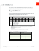


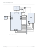
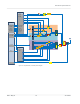
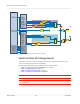
Table Of Contents
- Important Notice
- Safety and Hazards
- Limitation of Liability
- Contents
- List of Tables
- List of Figures
- 1: Introduction
- 2: Electrical Specifications
- 3: RF Specifications
- 4: Power
- 5: Software Interface
- 6: Mechanical and Environmental Specifica- tions
- 7: Regulatory Compliance and Industry Certifi- cations
- A: Antenna Specification
- B: Design Checklist
- C: Testing
- AT Command Entry Timing Requirement
- Acceptance Testing
- Certification Testing
- Production Testing
- Functional Production Test
- Quality Assurance Testing
- Suggested Testing Equipment
- Testing Assistance Provided by Lantronix, Inc.
- IOT/Operator Testing
- Extended AT Commands for Testing
- D: Packaging
- E: References
- F: Acronyms

Rev 5 May.21
17
41113694
2: Electrical Specifications
The system block diagram in Figure 2-1 represents the EM7411 module integrated into a
host system. The module includes the following interfaces to the host:
•
Full_Card_Power_Off#— Input supplied to the module by the host— active-low to turn
the unit off, or active-high to turn the unit on.
•
W_DISABLE1#— Active low input from the host to the EM7411 disables the main RF
radio.
•
W_DISABLE2#— Active low input from the host to the EM7411 disables the GNSS
radio receiver.
•
WAKE_ON_WAN#—Active low output used to wake the host when specific events
occur.
•
WWAN_LED#—Active-low LED drive signal provides an indication of WAN radio ON
state.
•
RESET#—Active low input from the host used to reset the module.
•
Antenna— Three RF connectors (main (Rx/Tx), GNSS, and auxiliary (diversity/MIMO/
GNSS)). For details, see RF Specifications on page 36.
•
Antenna control— Four signals that can be used to control external antenna switches.
•
Dynamic power control—Signal used to adjust Tx power to meet FCC SAR require-
ments. For details, see Tx Power Control on page 52.).
•
Dual SIM— Supported through the interface connector. The SIM cavities / connectors
must be placed on the host device for this feature.
•
SIM detect—Internal pullup on the module detects whether a SIM is present or not:
·
If a SIM is not inserted, the pin must be shorted to ground.
·
If a SIM is present, the pin will be an open circuit.
•
USB— USB 2.0 and USB 3.0 interfaces to the host for data, control, and status infor-
mation.
The EM7411 has two main interface areas— the host I/O connector and the RF ports.
Details of these interfaces are described in the sections that follow.
2