
Users Manual Part 2

FOX3-2G/3G/4G HARDWARE MANUAL VERSION 2.2.5
This confidential document is a property of Lantronix and may not be copied or circulated without previous permission.
Page 42 of 48
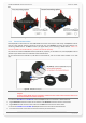
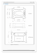
Figure 25: View of the mounting holes
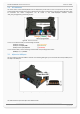
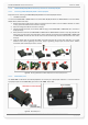
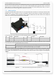
7.6.1. External Antenna Ports
FOX3-2G/3G/4G are fitted with two male SMB FAKRA connectors that accept a wide variety of GSM/GNSS antenna
styles for using external antennas instead of the internal ones. The Bordeaux connector (see figure below) is for
connecting a GSM antenna. The Blue connector (see figure below) is for connecting a GNSS antenna. There is no
antenna included in the standard delivery, it needs to be ordered separately.
We provide two combined GSM/GNSS antenna (FAL-ANT11) especially, for the FOX3 series, the 2G/3G/GNSS antenna
(FAL-ANT-12) for FOX3-3G series and FAL-ANT-14 for FOX3-4G Series.
For more details about the FAL-ANT-11, FAL-ANT-12 and FAL-ANT-14, refer to the data sheet available on our web
page.
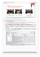
Figure 26: GSM/GPS antenna ports
CAUTION : Be careful not to accidental swap the GSM and GPS connectors. The device will not function if the antennas are
swapped.
In order to comply with RF exposure requirements, install the antenna so that a distance minimum of 20 cm can
be maintained between the antenna and persons.
To connect the FAL-ANT-11 or FAL-ANT-12 combined GSM/GPS antenna to the FOX3 or FOX3-3G devices:
Plug the Bordeaux-coloured connector of the antenna to the Bordeaux coloured connector of the device.
Plug the Blue-coloured connector of the antenna to the Blue coloured connector of the device.
To remove the FAL-ANT-11 or FAL-ANT-12 GSM/GPS antenna from the FOX3 or FOX3-3G devices:
Press down the latches on the antenna connectors and then pull the antennas.