
Users Manual Part 2

FOX3-2G/3G/4G HARDWARE MANUAL VERSION 2.2.5
This confidential document is a property of Lantronix and may not be copied or circulated without previous permission.
Page 41 of 48
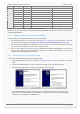
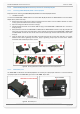
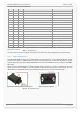
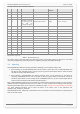
This table shows the pinout of IOBOX-CAN/WLAN.
PIN NAME I/O DESCRIPTION Main function
Alternative
function
LEVEL
1
V5CAN
O
Power Supply Output
-
-
Vout = 5V DC ; Imax ≤ 50mA
2
IN1
I
Digital/Analogue input
Analogue 10-bit resolution
Digital
0 V DC .. +52.0 V DC
3
GND
-
Ground
0 V
4 IN2 I
Digital/Analogue input.
Alternative as D8 data
input (reading live data
from VDO and
Stoneridge tachographs)
Analogue 10-bit resolution Digital 0 V DC .. +52.0 V DC
5
OUT1
O
Open collector output*
Output
-
100 mA max. @ 0 .. +32.0V DC
6
IN3
I
Digital/Analogue input
Analogue 10-bit resolution
Digital
0 V DC .. +52.0 V DC
7
OUT2
O
Open collector output*
Output
-
100 mA max. @ 0 .. +32.0V DC
8
IN4
I
Digital/Analogue input
Analogue 10-bit resolution
Digital
0 V DC .. +52.0 V DC
9
OUT3
O
Open collector output*
Output
-
100 mA max. @ 0 .. +32.0V DC
10
CAN_H
I/O
CAN HIGH-level
-
-
-
11
OUT4
O
Open collector output*
Output
-
100 mA max. @ 0 .. +32.0V DC
12
CAN_L
I/O
CAN LOW-level
-
-
-
13
K-LINE
I/O
Currently not supported
-
-
-
14
L-LINE
O
Currently not supported
-
-
-
15
VCAN
I
Currently not used
-
-
16
GND_CAN
-
Ground
-
-
0 V
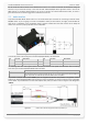
* It is strongly recommended to connect a separate flyback diode across the high inductive loads (e.g. relay). For details, refer to the connection
diagram shown in Figure 10.
Table 12: IOBOX-CAN/WLAN pinout
The indices of these inputs and outputs and information how to use this CAN interface can be found in the manual
"AVL_PFAL_Configuration_Command_Set.pdf" and "AppNote_CAN_FMS_CAN_OBDII_Howto.pdf".
7.6. Mounting
FOX3-2G/3G/4G offer different mounting possibilities, depending on the kind of the antenna used.
1. When installing one of FOX3-2G/3G/4G with internal antennas, please make sure the FOX3-2G/3G/4G' back
side with the text "THIS SIDE TO SKY" is facing up to the sky, with no metal objects above or under the device
case that can interfere with GPS reception.
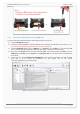
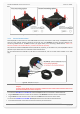
2. When installing a FOX3-2G/3G/4G with external antennas, there are two connectors on the device for
connecting a GPS/GNSS antenna such as FAL-ANT-11 (shown in figure below) or FAL-ANT-12. During the
installation, please make sure the receiving side of the GSM/GPS antenna is up, with no metal object above or
under the antenna and device that interfere with GPS reception.
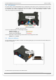
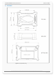
Each of FOX3-2G/3G/4G provide 8 holes to be attached to suitable locations (see figure below). It can be mounted in
different directions and different locations such as on wall or in vehicle. Fasteners can be Hexagon head with collar
self drilling screws DIN 7504 K, ST3.5 x 32(12) mm and different length. There are no screws included in the delivery
pack. More detailed information how to install the device in the vehicle, refer to the application note
"AppNotes_AVL_Installation_Guide.pdf".
FOX3-2G/3G/4G are NOT waterproof or sealed devices. Care must be taken to ensure the devices are kept away from
water or any other liquids.