
Users Manual Part 2

FOX3-2G/3G/4G HARDWARE MANUAL VERSION 2.2.5
This confidential document is a property of Lantronix and may not be copied or circulated without previous permission.
Page 36 of 48
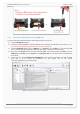
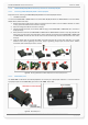
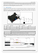
7.4. LED indicators
The actual state of the FOX3-2G/3G/4G can be displayed by three LED’s on the front panel of the unit. These
programmable and accessible LEDs can be interfaced to the build-in components to show their state. References how
to customize the device configuration can be found in the FOX3-2G/3G/4G software manual
“AVL_PFAL_Configuration_Command_Set.pdf”.
Figure 16: View of LED indicators
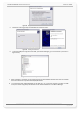
To turn on one of these LEDs, use the following command:
$PFAL,IO11.Set=high // 11=LED Orange;
$PFAL,IO12.Set=hpulse,2000 // 12=LED Green;
$PFAL,IO13.Set=cyclic,2000,1000 // 13=LED Red;
To turn off these LEDs, use the following command with corresponding index number:
$PFAL,IO[11,12,13].Set=low
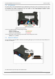
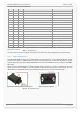
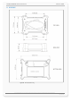
7.5. 10pin mini-USB port
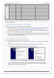
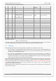
This port supports a SPI and a USB 2.0 interface. The following table gives you an overview about the provided pins on
this 10pin mini-USB-port.
Figure 17: Pin assignments of the 10pin mini-USB port.
This table shows the pinout of 10pin mini-USB connector.