
Users Manual Part 2


FOX3-2G/3G/4G HARDWARE MANUAL VERSION 2.2.5
This confidential document is a property of Lantronix and may not be copied or circulated without previous permission.
Page 45 of 48
9. APPENDIX
9.1. Schematics
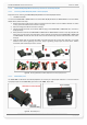
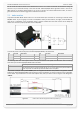
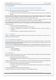
The figure below illustrates a common schematic of how to install the FOX3-2G/3G/4G devices in the vehicle. For
detailed information, refer to the related documents [AppNotes_AVL_Installation_Guide.pdf].
9.1.1. Installation guidance
When installing the FOX3-2G/3G/4G in a vehicle, you will be able to track and locate the vehicle all the time and also
you will be automatically notified when disagreements with your stored configuration into the FOX3-2G/3G/4G device
are occurred. Depending on the user requirements, the operator may program the digital outputs to activate
something e.g. a relay, buzzer, turn on a lamp, etc. The digital inputs can individually be configured e.g. to detect
something when it is opened or closed; changes on digital inputs may trigger an output to activate, for example, a
relay or buzzer. The IGN line can be connected to the vehicle ignition key to monitor its ON/OFF position.
Note: Turn the car ignition off before making any connection. Use a common ground point for all device ground
pins. To avoid ground loops and second grounds, isolate all grounded pins of the FOX3-2G/3G/4G from
the vehicle body. Do not connect power from a different system to the FOX3-2G/3G/4G.
The outputs of the FOX3-2G/3G/4G devices must be supplied with the same voltage applied to the (+IN)
pin. The operating voltage MUST never exceed its range, due to the device is not protected again
continuous overvoltage. For security reasons, it is recommended to integrate an external 2A fuse
between the positive wire of the FOX3-2G/3G/4G (+IN) and d.c. - power source.
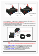
When using an external antenna, be sure to mount it on the dash or on the windshield of the vehicle with
the GPS side facing the sky.
Apply power to the FOX3-2G/3G/4G devices only with external antenna connected (if used) and vehicle
ignition off. First, connect the GND pin and finally, apply power to the +IN pin of the FOX3-2G/3G/4G.
Figure 29: Schematic example of installation guidance.
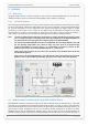
9.2. What should be considered when using FOX3-2G/3G/4G device
FOX3-2G/3G/4G are devicea controlled by means of the PFAL commands which are developed by us. These PFAL
commands can be executed when the operating firmware inside the device is running. In order to create application
with the FOX3-2G/3G/4G devicea and to obtain maximum benefit from the FOX3-2G/3G/4G operating firmware, you
have to setup a specific configuration and store it in the device. All PFAL commands can be sent to the FOX3-
2G/3G/4G with the help of the Workbench software, which is free of charge and can be downloaded from our
website. All PFAL commands supported by the FOX3-2G/3G/4G and other AVL devices are listed and described in a