
Users Manual Part 1

FOX3-2G/3G/4G HARDWARE MANUAL VERSION 2.2.5
This confidential document is a property of Lantronix and may not be copied or circulated without previous permission.
Page 9 of 48
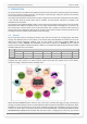
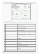
1.4. Circuit concept
The architecture of the FOX3-2G/3G/4G devices consist of the following major components (as shown below):
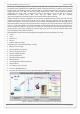
Architecture Integrates
- Quad-Band GSM/GPRS module or 3G module
- GNSS receiver (GPS + GALILEO + GLONASS) - GLONASS needs to be activated
- ARM7 processor controlling system functions
- Inside SIM card holder (1.8/3V SIM cards)
- Internal GSM/GNSS antennas
- Main Port (Power, RS232 port, I/O ports)
- Accessory Port (1-Wire, RS232 port, I²C interface)
- 10pin mini-USB-connector (incl. SPI & USB)
- Audio connector (Microphone & Speaker) - for FOX3 & FOX3-3G-AUDIO & FOX3-4G-NA
- GSM & GNSS antenna ports (for external antennas)
Physical Interfaces
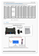
FOX3-2G/3G/4G accessories and hardware PREMIUM features
- 1 x Power supply lines
- Backup battery 1000 mAh (B1 Option)
- 3 x Multi-line I/O
- IOBOX-MINI - I/O extension module
- 1 x Ignition
- IOBOX-CAN - Second CAN-Bus interface
- 3 x LED indicators
- Car installation cable (more cables in the Ordering Guide)
- 2 x RS232 port (RX, TX, GND) V24
- CAN-Bus Interface
- 1 x 2.5mm audio port (not available on all models)
- 1 x USB port
- 1 x SPI interface (for IOBOX-MINI/ BT / CAN)
- 1 x 1-Wire port
- 1 x I²C port
- 2 x External antenna port
- 8 x Mounting Holes
Table 2: FOX3-2G/3G/4G architecture