
Users Manual Part 1


FOX3-2G/3G/4G HARDWARE MANUAL VERSION 2.2.5
This confidential document is a property of Lantronix and may not be copied or circulated without previous permission.
Page 31 of 48
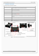
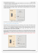
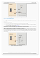
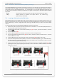
Figure 11.1: Use IGN line to wake FOX3-2G/3G/4G up from IGN-Sleep
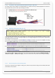
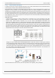
7.1.3.5. Serial Port 0 - Serial communication signals (RxA and TxA)
FOX3-2G/3G/4G devices incorporates a full duplex serial channel which allows two devices to communicate directly
with each other via the RS232 serial port. All supported variable baud rates are software-controlled. It is
recommended to use the FOX3-2G/3G/4G Evalboard in order to communicate with the FOX3-2G/3G/4G devices, since
you will find there all you need to evaluate with it. The signals on these pins are obtained to RS232 compatible signal
levels.
RxA_0 Main channel used to receive software commands to the board from any
software (e.g. HyperTerminal). Moreover, the firmware update can also be done
through this serial port.
TxA_0 Main channel used to output navigation, measurement, response and system
data to any software (e.g. HyperTerminal, Workbench).
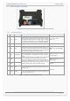
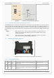
7.2. Accessory Port (6pin connector)
Figure 12: Pin assignments of 6-pin (2x3) connector (Type: MOLEX-43045-06-MICRO FIT)
7.2.1. Accessory Port Pinout
PIN
NAME
DIRECTION
DESCRIPTION
LEVEL
1 1-Wire
Input
/Output
1-Wire master interface for Driver ID, temperature and
humidity sensors.
VOUT = + 2.8 .. +5.0 V
2
GND
-
Ground Reference.
0 V
3 RxA_1 Input
(Serial Port 1) Serial port (receive data) for direct connection to
the host PC (configuration, evaluation, firmware). If not used
leave it open.
V24, ±12 V