
Users Manual Part 1

FOX3-2G/3G/4G HARDWARE MANUAL VERSION 2.2.5
This confidential document is a property of Lantronix and may not be copied or circulated without previous permission.
Page 29 of 48
respectively. Detailed information about PFAL commands can be found in software manual
“AVL_PFAL_Configuration_Command_Set.pdf“.
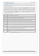
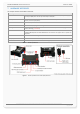
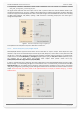
The figure below illustrates how these inputs can be used in practice. When the internal software detects input
changes from High to Low or vice versa, a Falling or Rising edge Event is respectively generated. Therefore, depending
on the alarm type, the FOX3-2G/3G/4G can react to the input changes and release different alarms such as sending
out SMS, email messages, TCP packets, opening a CSD connection or activating output ports. The alarm type is
configuration-dependant.
Figure 9: Connection example when using it as digital input.
A completed circuit example for all inputs is attached in section 9.1.1.
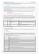
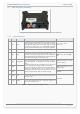
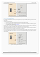
7.1.3.3. How to use I/O pins (4, 5, 6) as digital outputs
FOX3-2G/3G/4G devices support three IOs which can be used either as input or output. These outputs are open
collectors. They can be connected directly via resistors (R) to LEDs, Relays etc., which need no more power than 100
mA @ up to + 32.0 V DC. The figures below show the schematic of possible output connections. To activate these
outputs use the command $PFAL,IO4[5,6].Set=high[low,hpulse,lpulse,cyclic] for IO1, IO2 and IO3 respectively or you
can configure one or more alarms that activate these outputs when specific events occur (e.g.
$PFAL,Cnf.Set,AL0=IO.e8=redge:IO4.Set=cyclic,1000,2000).
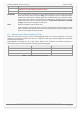
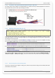
In order to evaluate this alarm, send firstly this alarm configuration to the FOX3-2G/3G/4G devices and then trigger
IGN-pin to High – as result the IO1 goes High for 1 sec and Low for 2 sec. To set IO1 to Low, just execute the command
PFAL,IO4.Set=Low. For more details how to activate an output and how to configure an alarm, refer to the manual
“AVL_PFAL_Configuration_Command_Set.pdf“. Both figures below show the schematic connections of how to use this
output. Please note that, the power should not be applied directly to an output pin without having e.g. a resistor
between them.
Figure 10: Connection example 1 when using it to control an Relay.