
Users Manual Part 1

FOX3-2G/3G/4G HARDWARE MANUAL VERSION 2.2.5
This confidential document is a property of Lantronix and may not be copied or circulated without previous permission.
Page 28 of 48
Analog voltages of up to 32.0V with a 10 bits resolution can be processed and remotely evaluated by a server
application. A pull-up resistor to a constant input voltage allows for resistive transducers to ground, e.g. fuel sensor or
thermistors.
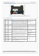
To use these IOs as analog inputs, send the following command to the device.
$PFAL,IO0[1,2].Config=AI,2,11
where 0, 1 and 2 are indices corresponding to IO1 (pin 4), IO2 (pin 5) and IO3 (pin 6), respectively. While the value
2 and 11 are min. and max. voltages that will be used to generate Low and High events, respectively. Detailed
information can be found in the software manual “AVL_PFAL_Configuration_Command_Set.pdf“.
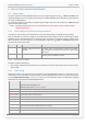
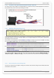
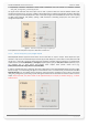
Connection example 1 (for I/O1 and I/O2):
An analog input can be connected to a temperature sensor (a NTC resistor for instance). In the diagram below is
used a fixed resistor from the input voltage to the I/O2, and a variable resistor (Negative Temperature Coefficient
- whose resistance or capacitance decreases when temperature increases) to ground. It is possible to set a low
temperature alarm and a high temperature alarm. Passage through these thresholds will trigger an alarm. We
recommend to use SMS or TCP as alarm type with GPIOP protocol. The SMS can be received on a mobile phone,
modem or any GSM device when changes are detected. The analog-to-digital converter (ADC) inside the unit has
an input voltage range from 0 to 2.5 V. An application example is shown in figure below:
Figure 8: Connection example 1 when using it as analog input.
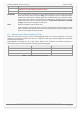
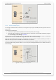
Connection example 2 (for I/O1 and I/O2):
An analog input can be connected to a tachometer generator. The maximum output voltage of the
tachometer should be + 32.0 V (see illustrated example in figure below).
Both circuit examples (the NTC diagram above and the Tachometer below) are only illustrations to show the aim of
these I/Os when using them as analog inputs.
Figure 8.1: Connection example 2 when using it as analog input.
7.1.3.2. How to use I/O pins (4, 5, 6) as digital Inputs
These pins are high active when used as digital inputs, so you can set V
IN(LOW)
and V
IN(HIGH)
to any levels within the
range from +0 to +32.0 VDC. The High and Low levels can be set with PFAL command (e.g.
PFAL,IO0[1,2].Config=DI,5,10) - where 0, 1 and 2 are indices corresponding to IO1 (pin 4), IO2 (pin 5) and IO3 (pin
6) respectively. The values 5 and 10 are min. and max. voltages that will be used to generate Low and High events