
Users Manual Part 1

FOX3-2G/3G/4G HARDWARE MANUAL VERSION 2.2.5
This confidential document is a property of Lantronix and may not be copied or circulated without previous permission.
Page 27 of 48
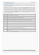
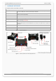
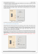
7.1.2. Installation cable (KA70-FOX3-2G/3G/4G-KFZ-INST-1,5M-2x4)
This cable, which is NOT included in the standard delivery, is needed to install your FOX3-2G/3G/4G to the vehicle. If
you need this cable, you can order it by contacting your vendor.
Figure 7: FOX3-2G/3G/4G installation cable (KA70-FOX3-2G/3G/4G-KFZ-INST-1,5M-2x4).
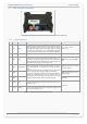
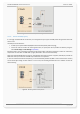
7.1.3. Special pin description (Pins 4, 5, 6)
The I/O2 and I/O3 (pin 5 and 6) can also operate as CAN-Bus interface if CAN is activated on the FOX3-2G/3G/4G devices. More
details about the CAN interface can be found in the PDF-files:
1) AVL_PFAL_Configuration_Command_Set.pdf,
2) AppNotesForCANBusApplication_xxx.pdf and
3) AppNote_CAN_FMS_CAN_OBDII_Howto_vxxx.pdf.
These pins have dual functions. All are controlled by the internal firmware of FOX3-2G/3G/4G. Therefore, the user
must define whether to use them as analog or digital pins. The configured digital pins can be inputs or outputs while
the analog pins can only be inputs.
Their function is controlled by the command PFAL,IO0[1,2].Config. For example, if you want to use I/O1 as an analog
pin, and the I/O2 and I/O3 as digital , then use the following commands respectively:
$PFAL,IO0.Config=AI,2,11 // 0 = I/O1; AI = analog; 2 and 11 = min. and max. voltages for Low and High events
$PFAL,IO1.Config=DI,5,10 // 1= I/O2; DI = digital input; 5 and 10 = min. and max. voltages for Low and High events
$PFAL,IO2.Config=DI,5,10 // 2= I/O3; DI = digital input; 5 and 10 = min. and max. voltages for Low and High events
If you want to use a digital pin, e.g. I/O2 or I/O3, as an digital output pin, then use the following PFAL command:
$PFAL,IO4.Set=high //4= I/O1; high = sets output to high
$PFAL,IO5.Set=high //5 = I/O2; high = sets output to high
$PFAL,IO6.Set=cyclic,2000,1000 //6 = I/O3; cyclic = sets output to high for 2 seconds and low for 1 seconds.
Some examples how to use them are given in the sections below.
When using an I/O as digital pin you must set it first to high (with PFAL command “$PFAL,IO4.Set=high” or
“$PFAL,IO5.Set=high” or “$PFAL,IO6.Set=high”), otherwise 0V will be measured (and the device could get damaged).
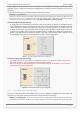
7.1.3.1. How to use I/O pins (4, 5, 6) as analog inputs
These pins can operate either as digital or analog inputs, however they should be configured and calibrated with PFAL
commands for such purposes.