
Users Manual Part 1

FOX3-2G/3G/4G HARDWARE MANUAL VERSION 2.2.5
This confidential document is a property of Lantronix and may not be copied or circulated without previous permission.
Page 26 of 48
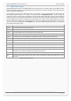
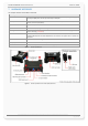
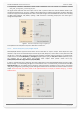
7.1. Main Port (8pin connector)
Figure 6: Pin assignments of 8-pin (2x4) connector (Type: MOLEX-43045-08-MICRO FIT)
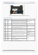
7.1.1. Main Port Pinout
PIN
NAME
DIRECTION
DESCRIPTION
LEVEL
1 +IN Input
Power supply input. The power supply must be able to meet the
requirements of current consumption. Care must be taken so that the
operating voltage, applied to the device, stay within the voltage
range. Applying a voltage outside of the voltage range can damage
the device. For security reason, it is recommended to integrate
externally a 2A fuse link between power source and FOX3-2G/3G/4G.
V
+IN
= + 10.8 ... + 32.0 V
Imax ≤ 1.5 A
2
GND
-
Ground.
0 V
3 IGN Input
General purpose input. It can be either connected to the vehicle
ignition and be used for journey START and STOP reports, or be
connected to the operating voltage +IN and be used to wakeup the
FOX3-2G/3G/4G devices from IGN-Sleep mode (awaking from this
mode requires a HIGH signal)
. See also chapter 7.1.3.4.
HIGH ≥+10.8 .. +32.0 V DC; LOW =
0V
4 I/O1 Input/Output
Software configurable pins. Each pin has dual functions as analog or
digital. Each digital pin can individually be set either as input or
output.
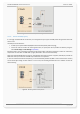
Every time the device starts up, a level change occurs on the I/O2 and
I/O3 pins. Only I/O1 doesn't change the level on device start up.
Pins I/O2 and I/O3 support CAN communication if this interface is
activated. The CAN-
Bus interface can be activated using the
corresponding PFAL command (see PFAL command set for more
details). In this case the I/O2 = CAN_L and the I/O3 = CAN_H).
OUT: 100 mA max. @ +0 .. +32.0V
DC (open collector)
5 I/O2
IN: 0 V..+32.0V DC
(High & Low levels are free-
programmable)
6 I/O3
Analog : Up to 32.0 V DC/10 bits
resolution
7 RxA_0 Input
(Serial Port 0) The serial port (receive data) for direct connection to
the host PC (for configuration, evaluation, firmware). If this pin is not
used leave it open.
V24, ±12 V
8 TxA_0 Output
(Serial Port 0) Serial port (transmit data) for direct connection to the
host PC (for transmitting history data, output GPS protocols and
more). If not used leave it open.
Table 8: Description of the main port (8-pin connector)