THIS DOCUMENT IS AVAILABLE ONLINE . FOX3-2G Series FOX3-3G Series FOX3-4G Series HARDWARE MANUAL Version: 2.2.
FOX3-2G/3G/4G HARDWARE MANUAL VERSION 2.2.5 Table of contents 1. Introduction ......................................................................................................................... 6 1.1. General......................................................................................................................................................... 6 1.2. FOX3-2G/3G/4G/4G Series hardware differences .......................................................................................
FOX3-2G/3G/4G HARDWARE MANUAL VERSION 2.2.5 7.1.3.2. How to use I/O pins (4, 5, 6) as digital Inputs ............................................................................................................ 28 7.1.3.3. How to use I/O pins (4, 5, 6) as digital outputs ......................................................................................................... 29 7.1.3.4. How to use IGN pin (pin 3) ..............................................................................................
FOX3-2G/3G/4G HARDWARE MANUAL VERSION 2.2.5 Version history: This table provides a summary of the document revisions. Version Author Changes Modified 2.2.5 F. Beqiri - Added ISED RF Exposure information in both English and French – see chapter 10 - Changed company logo to Lantronix. 08/14/2019 2.2.4 F. Beqiri - The wakeup condition on “CAN” is only supported with command $PFAL,Sys.Device.Doze. 02/13/2018 2.2.3 F.
FOX3-2G/3G/4G HARDWARE MANUAL VERSION 2.2.5 Cautions The information furnished herein by Lantronix is believed to be accurate and reliable. However, no responsibility is assumed for its use. Please, read carefully the safety precautions. If you have any technical questions regarding this document or the product described in it, please contact your vendor. General information about Lantronix and its range of products are available at the following Internet address: http://www.lantronix.
FOX3-2G/3G/4G HARDWARE MANUAL VERSION 2.2.5 1. INTRODUCTION This product manual is only addressed to qualified personnel who are well skilled in electronical/electrical installation and not to the private consumers/end users. The installation, implementing or setting into operation of the product can be performed only by qualified personnel.
FOX3-2G/3G/4G HARDWARE MANUAL VERSION 2.2.5 Geo-fencing. The FOX3-2G/3G/4G units are delivered without SIM card and without battery. SIM cards must first be purchased and then registered into the GSM network before installing into the device. The battery can be ordered as an option (refer to the Ordering Guide for more information). The setup and configuration of the device is provided through Serial Ports, over SMS and TCP using special commands like “PFAL” and the Workbench Software configuration tool.
FOX3-2G/3G/4G HARDWARE MANUAL VERSION 2.2.5 1.2. FOX3-2G/3G/4G/4G Series hardware differences The following table shows the hardware differences between FOX3-2G/3G/4G/-4G Series.
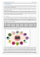
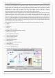
FOX3-2G/3G/4G HARDWARE MANUAL VERSION 2.2.5 1.4. Circuit concept The architecture of the FOX3-2G/3G/4G devices consist of the following major components (as shown below): Architecture Integrates - Quad-Band GSM/GPRS module or 3G module - GNSS receiver (GPS + GALILEO + GLONASS) - GLONASS needs to be activated - ARM7 processor controlling system functions - Inside SIM card holder (1.
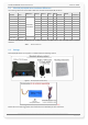
FOX3-2G/3G/4G HARDWARE MANUAL Figure 4: VERSION 2.2.5 FOX3-2G/3G/4G block diagram 1.5. Related documents In addition to this document, the following files comprise the full set of FOX3-2G/3G/4G product manuals: NR PDF file name Description [1] AVL_PFAL_Command_Set.pdf Contains the description of the internal firmware and the supported Configuration Command Set for the AVL devices. [2] AppNotes_Transform_history_data.
FOX3-2G/3G/4G HARDWARE MANUAL NR PDF file name VERSION 2.2.5 Description Series. [16] AppNote_IOBOX-CAN_D8_Interface_HowTo.pdf Provides information on how to configure your FOX3 series devices in combination with the accessory box IOBOX-CAN/WLAN, connect the IOBOX-CAN/WLAN to D8 connector of the digital tachograph, read real time data from this interface and transfer them to your platform server. [17] AppNote_IOBOX_WLAN_HowTo.
FOX3-2G/3G/4G HARDWARE MANUAL VERSION 2.2.5 2. DISCLAIMER This section explains our disclaimer concerning any application the customer may develop with AVL devices. (1) Due to the large variety of supported applications with AVL devices, We are not able to test all such types of applications. (2) The customer is solely responsible for proper use of the products and for a long-term test of the developed applications.
FOX3-2G/3G/4G HARDWARE MANUAL VERSION 2.2.5 3. SECURITY IMPORTANT FOR THE EFFICIENT AND SAFE OPERATION OF YOUR GSM-MODEM, READ THIS INFORMATION BEFORE USE! Your cellular engines FOX3-2G/3G/4G are one of the most exciting and innovative electronic products ever developed. With them, you can stay in contact with your office, your home, emergency services and others, wherever service is provided. This chapter contains important information for the safe and reliable use of the FOX3-2G/3G/4G devices.
FOX3-2G/3G/4G HARDWARE MANUAL VERSION 2.2.5 3.7. Aircraft Turn your FOX3-2G/3G/4G OFF before boarding any aircraft. Use them on the ground only with crew permission. Do not use them in the air. To prevent possible interference with aircraft systems, Federal Aviation Administration (FAA) regulations require you to have permission from a crew-member to use your modems while the plane is on the ground.
FOX3-2G/3G/4G HARDWARE MANUAL VERSION 2.2.5 3.11.1. Safety precautions while charging the battery Be sure to follow the rules listed below while charging the battery. Failure to do so may cause the battery to become hot, rupture, or ignite and cause serious injury. • When charging the battery insure that the battery charging conditions specified are met. The temperature range over which the battery can be charged is 0°C to 40°C. Charging is interrupted, if the ambient temperature is outside of this range.
FOX3-2G/3G/4G HARDWARE MANUAL VERSION 2.2.5 4. SAFETY STANDARDS Your GSM/GPRS/3G/4G/GNSS devices complies with all applicable RF safety standards. FOX3-2G/3G/4G meet the safety standards for RF receivers and the standards and recommendations for the protection of public exposure to RF electromagnetic energy established by government bodies and professional organizations, such as directives of the European Community, Directorate General V in matters of radio frequency electromagnetic energy.
FOX3-2G/3G/4G HARDWARE MANUAL VERSION 2.2.5 5. TECHNICAL DATA 5.1. Product features Supply voltage range: Operating power supply voltage range of +10.8 V to +32.0 V, suitable for direct connection to an automotive +12V or +24V DC power source (vehicle battery). 10 different energy-saving modes - programmable with PFAL commands. See chapter 6.1.3 for more details. Power saving: Operating temperature range: - 40°C to + 85°C (see chapter 5.1.2 for more details).
FOX3-2G/3G/4G HARDWARE MANUAL Accessories (to be ordered separately - see ordering guide): Backup Li-Polymer battery Car Installation Cable Accessory Installation Cable GSM/GNSS quad-band external antenna (FAL-ANT-11) for FOX3 GSM/GNSS penta-band external antenna (FAL-ANT-12) for FOX3-3G GSM/GNSS penta-band external antenna (FAL-ANT-14) for FOX3-4G IOBOX-MINI (external I/O extension device - up to 13 inputs/outputs) IOBOX-CAN (external device with 2nd CANBus interface and
FOX3-2G/3G/4G HARDWARE MANUAL 5.1.1. VERSION 2.2.5 Power consumption for FOX3-2G/3G/4G All measurements have been performed with Tamb= 23°C, VIN+ = 12 V DC; FOX3: DCS 1800 MHz, Power Level 10, Cell Power -75dBm; FOX3-3G: UMTS 2100 Mhz; Average power consumption @ +12 V Modes Comments FOX3-2G FOX3-3G FOX3-4G Unit Max. >1 >1 >1 A In a transmit burst the current consumption can rise to typical peaks of 1A CPU on / GPS on / GSM off 38 41 61 mA GPS-fix valid.
FOX3-2G/3G/4G HARDWARE MANUAL 5.1.2. VERSION 2.2.5 Operating temperatures Parameter Min. Typ. Max. Unit Storage temperature -40 +25 85 °C Storage temperature -20 +25 +60 °C Operating temperature -40 +25 +85 °C GSM* -30 +25 +80 °C Charging temperature (battery-operated **) 0 +25 +45 °C Discharging temperature (battery-operated **) -20 +25 +60 °C * The GSM/GPRS module is fully functional (-20 °C to + 55 °C meets the 3GPPspecifications). ** Optional.
FOX3-2G/3G/4G HARDWARE MANUAL SMS: Text mode. Offers a choice of 19 different ringing tones/melodies, easily selectable with PFAL commands. Ring tones: 5.1.4. VERSION 2.2.5 GNSS engine features GNSS engine: Multi channel GNSS (GPS/Galileo/GLONASS/BeiDou) receiver GPS L1 C/A code Accuracy: Position: SBAS: 2.5 m CEP 2 m CEP. Time to First Fix (TTFF): Hot starts: Cold starts: 1 sec. 26 sec. Tracking: Cold start: -161 dBm -148 dBm.
FOX3-2G/3G/4G HARDWARE MANUAL VERSION 2.2.5 5.2. NMEA data message FOX3-2G/3G/4G deliver data in the NMEA-0183 format and own format. The table below lists the NMEA and own supported protocols and gives also a brief description for each of them. For further description about these protocols, refer to the related documents [1]. These protocols can be sent via SMS, TCP, data call, serial port, e-mail or stored inside the device using the corresponding PFAL-Commands. For example, the PFAL-Command "PFAL,GSM.
FOX3-2G/3G/4G HARDWARE MANUAL VERSION 2.2.5 6. FOX3-2G/3G/4G APPLICATION INTERFACE 6.1. Power supply The power supply for the FOX3-2G/3G/4G devices has to be a single voltage source of V+IN = +10.8 V...+32.0 V DC. The operating voltage (V+IN) has to be applied permanently to the FOX3-2G/3G/4G devices and able to provide sufficient current of up to 1.5 A (pulse). The operating voltage (V+IN and GND) is protected against voltage spikes and reverse polarity, but NOT protected against continuous overvoltage.
FOX3-2G/3G/4G HARDWARE MANUAL Modes VERSION 2.2.5 Description supported only with $PFAL,Sys.Device.Doze. LowBat=3.6 Device wakes up when the battery voltage drops below the specified value IMPORTANT: The sleep and wake-up procedures are quite different depending on the selected sleep mode. Please note that the power saving with "Ring" works properly only when the PIN authentication has been done and the device is already registered in the GSM network.
FOX3-2G/3G/4G HARDWARE MANUAL VERSION 2.2.5 7. HARDWARE INTERFACES This chapter describes the hardware interfaces: Interface specifications Main Port The 8pin double-row connector, type: MOLEX-43045-08-MICRO FIT. It provides IN/OUT, power supply and first serial port (SER0) lines. The same pin functionality as FOX-IN/EN. Accessory Port The 6pin double-row connector, type: MOLEX-43045-06-MICRO FIT. It provides 1-Wire bus, I²C master interface, second serial port (SER1).
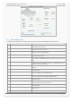
FOX3-2G/3G/4G HARDWARE MANUAL VERSION 2.2.5 7.1. Main Port (8pin connector) Figure 6: 7.1.1. PIN Pin assignments of 8-pin (2x4) connector (Type: MOLEX-43045-08-MICRO FIT) Main Port Pinout NAME DIRECTION DESCRIPTION LEVEL V+IN = + 10.8 ... + 32.0 V Imax ≤ 1.5 A 1 +IN Input Power supply input. The power supply must be able to meet the requirements of current consumption. Care must be taken so that the operating voltage, applied to the device, stay within the voltage range.
FOX3-2G/3G/4G HARDWARE MANUAL 7.1.2. VERSION 2.2.5 Installation cable (KA70-FOX3-2G/3G/4G-KFZ-INST-1,5M-2x4) This cable, which is NOT included in the standard delivery, is needed to install your FOX3-2G/3G/4G to the vehicle. If you need this cable, you can order it by contacting your vendor. Figure 7: 7.1.3. FOX3-2G/3G/4G installation cable (KA70-FOX3-2G/3G/4G-KFZ-INST-1,5M-2x4).
FOX3-2G/3G/4G HARDWARE MANUAL VERSION 2.2.5 Analog voltages of up to 32.0V with a 10 bits resolution can be processed and remotely evaluated by a server application. A pull-up resistor to a constant input voltage allows for resistive transducers to ground, e.g. fuel sensor or thermistors. To use these IOs as analog inputs, send the following command to the device. $PFAL,IO0[1,2].Config=AI,2,11 where 0, 1 and 2 are indices corresponding to IO1 (pin 4), IO2 (pin 5) and IO3 (pin 6), respectively.
FOX3-2G/3G/4G HARDWARE MANUAL respectively. Detailed information about PFAL “AVL_PFAL_Configuration_Command_Set.pdf“. VERSION 2.2.5 commands can be found in software manual The figure below illustrates how these inputs can be used in practice. When the internal software detects input changes from High to Low or vice versa, a Falling or Rising edge Event is respectively generated.
FOX3-2G/3G/4G HARDWARE MANUAL VERSION 2.2.5 Figure 10.1: Connection example 2 when using it to control an LED. 7.1.3.4. How to use IGN pin (pin 3) It is strongly recommended to connect this pin to the ignition key to support the IGN-power saving function when the vehicle is off.
FOX3-2G/3G/4G HARDWARE MANUAL Figure 11.1: 7.1.3.5. VERSION 2.2.5 Use IGN line to wake FOX3-2G/3G/4G up from IGN-Sleep Serial Port 0 - Serial communication signals (RxA and TxA) FOX3-2G/3G/4G devices incorporates a full duplex serial channel which allows two devices to communicate directly with each other via the RS232 serial port. All supported variable baud rates are software-controlled.
FOX3-2G/3G/4G HARDWARE MANUAL 4 TxA_1 Output (Serial Port 1) Serial port (transmit data) for direct connection to the host PC (transmitting history data, output GPS protocols and others). If not used leave it open. 5 SCL Output I2C bus interface - Serial Clock line – the signal used to synchronize communication between the master and the slave. 6 SDA Input /Output I2C bus interface - Serial Data line – the signal used to transfer data between the transmitter and the receiver. Table 9: VERSION 2.
FOX3-2G/3G/4G HARDWARE MANUAL 7.2.2. VERSION 2.2.5 1-Wire interface description A 1-Wire bus uses only one wire for signaling and power. One or several 1-Wire devices can be connected to the bus at the same time. Only one master should be connected to the bus. Driver identification, temperature and humidity sensors are quite often used on vehicle applications.
FOX3-2G/3G/4G HARDWARE MANUAL 7.2.2.1. VERSION 2.2.5 Serial Port 1 - Serial communication signals (RxA_1 and TxA_1) The FOX3-2G/3G/4G devices incorporate a full duplex serial channel in the accessory port which allows two devices to communicate directly via RS232 serial ports. All supported baud rate are controlled by PFAL commands.