Model Name: A104 (For Conexant Chipset) Version: 1.0 FCC Part 68 FCC Part 15 Chapter 1. Introduction Chapter 1.1 Overview Chapter 1.2 Features Chapter 1.3 System Requirements Chapter 2. Installation Chapter 2.1 Checklist Chapter 2.2 The Front LEDs Chapter 2.3 The Rear Ports Chapter 2.4 Hardware Installation Chapter 3 Configuration Chapter 3.1 Determine your connection setting Chapter 3.2 Connecting the ADSL Router to your network Chapter 3.3 Configuring with Web Browser Chapter 3.3.
Chapter 3.3.14 Admin Privilege - WAN Status Chapter 3.3.15 Admin Privilege - ATM Status Chapter 3.3.16 Admin Privilege - TCP Status Chapter 3.3.17 Admin Privilege - Route Table Chapter 3.3.18 Admin Privilege - Learned (Bridge) MAC Table Chapter 3.3.19 Admin Privilege - ADSL Configuration Chapter 3.3.20 Admin Privilege - RIP Configuration Chapter 3.3.21 Admin Privilege - Password Configuration Chapter 3.3.22 Miscellaneous Configuration Chapter 3.3.23 Reset to Factory Default Chapter 3.3.
advance. But if advance notice isn't practical, you will be notified as soon as possible. You will be advised of your right to file a complaint with the FCC. The telephone company may make changes in its facilities, equipment, operations, or procedures that could affect the proper operation of your equipment. If they do, you will be notified in advance to give you an opportunity to maintain uninterrupted telephone service.
Changes or modifications not expressly approved by the party responsible for compliance to the FCC Rules could void the user's authority to operate this equipment. All equipment connected to this modem must use shielded cable as the interconnection means. Operation is subject to the following two conditions: 1) This device may not cause harmful interference, and 2) This device must accept any interference received including interference that may cause undesired operation.
The CX82310 is built upon a scalable architecture and is fully compliant with full-rate ADSL (T1.413 Issue 2 and G.dmt standards) and the splitterless G.Lite (G.992.2) standards, including Annex A (ADSL over POTS) and Annex B (ADSL over ISDN). This broad level of compliance ensures that products based on the AccessRunner can address the existing installed base and continued deployment of ADSL lines. Telephone companies, for example, can deploy full-rate, splitterless full-rate as well as G.
- Tone detection for low power mode - Supports splitter less ADSL implementation - Supports Dying Gasp - Interoperable with all major DSLAM equipment ATM Protocols - WAN mode support: PPP over ATM (RFC 2364) and PPP over Ethernet (RFC 2516) - LAN mode support: bridged/routed Ethernet over ATM (RFC 1483) and classical IP over ATM (RFC 1577) - ATM Forum UNI 3.1/4.
- WAN and LAN side connection statistics - Configuration of static routes and routing table - Password protected access - Selection of bridge or router mode - PPP user ID and password - Configuration of VCs (virtual circuits) 1) Personal computer (PC) 2) Pentium II 233 MHz processor minimum 3) 32 MB RAM minimum 4) 20 MB of free disk space minimum 5) Ethernet Network Interface Controller (NIC) RJ45 Port 6) Internet Browser This chapter offers information about installing your router.
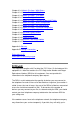
ON Modem is powered ON OFF Modem is powered OFF Flashing When the router is working properly ON Flashing OFF "Showtime"-successful connection between ADSL modem and telephone company's network "Handshaking"-modem is trying to establish a connection to telco's network Modem is powered OFF ADSL Carrier Detect if LED is flash Flashing Data transmitting between LAN AND PC ON Link Flashing Tx or Rx activity OFF No Link These four LAN (Local Area Network) ports are where you will connect networked
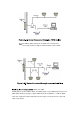
modem and the ADSL network through a twisted-pair phone wire This section describes how to connect and configure the ADSL router. Connect the router directly to the wall jack using the included ADSL cable. There are two methods to connect the router and workstation. The one use the crossover Ethernet cable to connect directly between them. The other use straight Ethernet cable to connect router with hub (or switch), then go to the workstation.
The POTS splitter may also be installed on the outside of the house adjacent to the telephone network interface device (NID). (ADSL over ISDN) A ISDN splitter separates ADSL signals from ISDN signals on your ISDN telephone line. The ISDN splitter works by running a separate ADSL line from the ISDN line, so that the ADSL router has a dedicated cable for data transmission. Figure 2-3.3 shows how to connect all cables to the Router.
The ISDN splitter may also be installed on the outside of the house adjacent to the telephone network interface device (NID). Before you configure the router, you need to know the connection information supplied by your ADSL service provider.
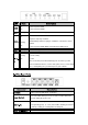
Gather the information as illustrated in the following table and keep it for reference.
LAN and VPI/VCI of WAN. Then save and reboot Router, it will work fine with your whole system. The computer should be set the fixed assigned IP address with the same domain at this mode. If your ISP provides RFC1483 Bridge mode plus PPPoE, it means the IP address of computer or router will be assigned automatically via PPPoE. There are two methods you can use at this mode. First you can set the "bridge" mode, give VPI/VCI of WAN and install PPPoE driver on your computer.
If you want to configure the device with administrator level, type username field and in the password field. If you want to configure the device with the user level, type username field and in the password field. in the in the Then, click to log in. You can modify these passwords for security and management purpose. At the configuration homepage, the left navigation pane where bookmarks are provided links you directly to the desired setup page.
The Home page shows the firmware versions and WAN and LAN interface status. This field display the Conexant firm ware (vxworks.z) version number. This field displays the customer' sown firmware version number and it is based on revision.txt. These fields display the IP address, Subnet Mask and MAC address for the WAN ADSL) interface. These fields display the IP address, Subnet Mask and MAC address for the LAN interface. This field displays the total number of available interfaces for the LAN interface.
The page shows the ADSL physical layer status. This field displays the Conexant ADSL data pump firmware version number. This field displays the ADSL connection process and status. This field displays the ADSL modulation status for G.dmt or T1.413. This field displays the ADSL annex modes for Annex A or Annex B. This field displays the ADSL connection attempts after loss of showtime. This field displays the transmit output power level of the CPE.
This field displays the time of the modem has been in operation. Amount of increased noise that can be tolerated while maintaining the designed BER (bit error rate). The SNR Margin is set by Central Office DSLAM. If the SNR Margin is increased, bit error rate performance will improve, but the data rate will decrease. Conversely, if the SNR Margin is decreased, bit error rate performance will decrease, but the data rate will increase.
These fields display the IP address, Subnet Mask and MAC address for the LAN interface. This field displays the total number of available interfaces for the LAN interface. These fields display the DHCP client table with the assigned IP addresses and MAC addresses. This field displays the link up or down for the Ethernet. This field displays the link up or down for the USB. The page shows the status of PPP for each PPP interface.
These fields display the Connection Name (user defined), Interface (PVC), Mode (PPPoE or PPPoA), Status (Connected or Not Connected), Packets Sent, Packets Received, Bytes Sent and Byte Received. This field allows the user to manually connect/disconnect the PPP connection for each PPP interface. In another word, each PPP session can be connected and disconnected individually. The configuration page allows the user to set the configuration for the WAN/ADSL ports.
To switch between the PVCs, please choose the options of virtual circuit and click on the button to switch over. The is developed to solve the scenario when the ISP only recognizes one MAC address. Copy the ISP-recognized MAC address here. UBR and CBR are supported from the ATM. Bandwidth setting takes effect only when the CBR is selected. The maximum available bandwidth is from the upstream data rate of ADSL status page (see Section 3.2, ADSL ).
The current release supports multiple PPP sessions per PVC. The PPP configuration in the WAN configuration page is for the first PPP session for each PVC. The predefined PPP Account Name (Account ID) is “Simple PPP Account 0” for PVC0 and predefined PPP Connection Name is “Simple PPP Session 0” for PVC0. For the other PVC X, the predefined account name and connection name will be Simple PPP Account X and Simple PPP Session X. X is the PVC number from 1 to 7.
When it is checked, it will maintain the PPP connection all the time. If the ISP shut down the PPP connection, it will automatically reconnect PPP session. When option is chosen, the PAP mode will run first then CHAP. Required by some ISPs. If the ISP does not provide the Host name, please leave it blank.
PVC General Multicast IP - Ignore The configuration page allows the user to set the configuration for the LAN port. The default is 10.0.0.2 and 255.0.0.0. User can change it to other private IP address, such as 192.168.1.2, and 255.255.255.0. The DHCP address pool is based on LAN port IP address plus 12 IP addresses. For example, the LAN IP address is 10.0.0.2; the DHCP address pool is at the range of 10.0.0.3 to 10.0.0.14. The DHCP address pool is at the range of and .
The configuration page allows the user to set the LAN port into Auto Sense, 100 Mbps Full Duplex, 100 Mbps Half Duplex, 10 Mbps Full Duplex or 10 Mbps Half Duplex. The page allows the user to configure multiple PPP sessions for each PVC. It can support up to total of 16 PPP sessions, and each PVC can support up to 8 PPP sessions. The multiple PPP sessions may be configured with any combination over 8 PVCs.
This field allows the user to enter his/her own session Name to distinguish different session for different PPP accounts and different PVCs. This field allows the user to choose the specific PVC for PPP session. The service name of PPP is required by some ISPs. If the ISP does not provide the Service Name, please leave it blank. The Disconnect Timeout allows the user to set the specific period of time to disconnect from the ISP. The default is 0, which means never disconnect from the ISP.
of the PPP connection will be set to the smaller one of MTU and the peer’s MRU. The default is value 1492. Maximum Segment Size is the largest size of data that TCP will send in a single IP packet. When a connection is established between a LAN client and a host in the WAN side, the LAN client and the WAN host will indicate their MSS during the TCP connection handshake. The default value is 1432. When it is checked, it will maintain the PPP connection all the time.
This field allows the user to enter his/her own account ID to distinguish different accounts. Enter the PPP user name (usually provided buy the ISP). Enter the PPP password (usually provided buy the ISP). will be displayed at the bottom of this page to show all the accounts with its Account Name and User Name. (It does not show the password.) This field displays the total number of PPP Accounts is entered. The page allows the user to set the configuration for the Network Address Translation.
Network Address Translation capability between LAN and multiple WAN connections, and the LAN traffic is routed to appropriate WAN connections based on the destination IP addresses and Route Table. This eliminates the need for the static NAT session configuration between multiple LAN clients and multiple WAN connections. When the Dynamic NAPT is chosen, there is no need to configure the NAT Session and NAT Session Name Configuration.
show the corresponding Session Name with its IP address. This filed displays the total number of NAT Sessions is entered. will be displayed at the end of this page to show all the Session Names with its WAN Interface. This filed displays the total number of NAT Sessions Name is entered. The option only maps single WAN IP address to the local PC IP address. It is peerto-peer mapping. (1x1) For each WAN interface, only one local PC IP address can be associated with each WAN interface.
page to show all the NAT Session Names with its WAN Interface. This filed displays the total number of NAT Sessions Name is entered. Click the link to the NAT configuration page. Select the option. Select the Session Name and assign the PC IP address, and choose the action. Click the button and go to the to save this configuration. The page allows the user to set the configuration of Virtual Server. The Conexant firmware includes the Free BSD version firewall.
This field allows the user to enter the port number of the Private Network. In most cases, the private port number is same as public port number. This field allows the user to enter the private network IP address for the particular sever. The page allows the user to set the configuration of DNS proxy. The Conexant firmware supports the DNS proxy function. For the DHCP requests from local PCs, the DHCP server will set the LAN port IP as the default DNS server.
The DNS proxy will store the DNS server IP addresses obtained from DHCP client or PPP into the table. And all DNS query messages will be sent to one of the dynamically obtained DNS servers. The DNS proxy will use the user-configured preferred DNS server and alternate DNS server. And all DNS query message will be sent to one of DNS servers. Enter the DNS IP in the Preferred DNS Server and Alternate DNS Server fields.
be filtered out. If the is selected, then the packets will be forwarded to the destination PC. When the bridge filtering is enabled, enter , select and click . Then all incoming WAN and LAN Ethernet packets matched with this destination MAC address will be filtered out. If the is selected, then the packets will be forwarded to the destination PC. Enter the hexadecimal number for the Ethernet type field in Ethernet_II packets. For example, 0800 is for IP protocol.
rebooted. Please wait….” After the Save and Reboot, the following Web page will be displayed “Your setting have been saved and the modem has rebooted.” The page allows the user to reboot the system without save the new configuration to the flash. During the Reboot, the following Web page will be displayed “The modem is being rebooted. Please wait….”. After the Reboot, the following Web page will be displayed “The modem has rebooted.” The page shows the information and status of WAN PVCs.
These fields display the IP address, Subnet Mask and MAC address for the WAN (ADSL) interface. This field allows the user to release and renew the WAN IP address in the WAN DHCP Client Enabled (dynamic) mode. The page shows all the statistics information of ATM cells.
: This button allows user to reset the ATM Status counter. The page shows the statistics for all TCP connections.
: This button allows user to reset the TCP Status counter. The page displays routing table and allows the user to manually enter the routing entry. The routing table will display the routing status of Destination, Netmask, Gateway, and Interface. The interface br0 means the USB interface; lo0 means the loopback interface; and ppp1 means the PPP interface.
The Gateway field of the static route entry allows users to either enter a Gateway IP address or select a Network Interface. All user-defined routes retained in the CPE memory, regardless if they are already in the Routing Table, are displayed on the same Route Table page. All user defined route entries kept in the CPE memory during run time are saved to flash when the user chooses to save and reboot the CPE.
Network Interface, then that Gateway’s IP address appears in the Gateway field of the route entry If the selected Network Interface is dynamic but the connection is not established, then the route entry does not appear in the Routing Table. When the interface comes up later, the route entry is then added. The system-wide Default Gateway now provides three options: Auto, User-selected Network Interface, and None.
This field allows the user to enter the update period for the MAC table. The ADSL protocols.
This field allows the user to enable or disable the Trellis Code. By default, it is always enabled. This field allows the user to select the ADSL handshake protocol. This field allows the user to enter the wiring selection for the RJ-11. Tip/Rip is the default for the board without the inner/outer pair relay This field allows the user to enable or disable the upstream bit swapping. The page allows the user to set the configuration for the system wide configuration of RIP.
This field allows the user to Enable or Disable the RIP session. The resulting RIP session will monitor all network interfaces that are currently available for messages from other RIP routers. This field allows the user to enter the Supplier Interval timer in second. This timer specifies how often RIP sends announcements as a RIP Supplier. This field allows the user to enter the Expire timer in second. This timer specifies the expiration time of a route.
This field allows the user to choose the Interface (PVCs, PPP Sessions, USB and LAN), for the RIP to be configured. This field allows the user to Enable (Yes) or Disable (No) the specified interface for RIP. This field allows the user to select the Supplier Mode (RIP Transmit). Disabled: The supplier transmit is disabled. V1 BC: The supplier transmits in RIPv1 Broadcast. V2 BC: The supplier transmits in RIPv2 Broadcast. V2 MC: The supplier transmits in RIPv2 Multicast.
status. The password for administrator. page allows the user to set the The Admin password is same pas the FTP password, so it must has at least 8-characters for the FTP to work. The for the user.
The miscellaneous configurations.
This field allows the user to configure the Web pages can be accessed from. When this field is checked, it allows both WAN and LAN access to the Web pages. This field allows the Web pages access from LAN side. This field allows the Web access from WAN side with a specify IP and subnet mask. This field allows the user to specify the port of the Web access. . For example, when it is changed to 1001, the HTTP server address for the LAN side is This field allows the user to enable or disable the FTP connection.
The IP address of the DMZ host at LAN side. If it is enabled, the DHCP requests from local PCs will forward to the DHCP server runs on WAN side. To have this function working properly, please disable the NAT to run on router mode only, disable the DHCP server on the LAN port, and make sure the routing table has the correct routing entry. The DHCP server runs on WAN side. Here is the global setting for IGMP Proxy. If it is enabled, then the enabled IGMP Proxy on WAN PVCs will be working.
The page shows the test results for the connectivity of the physical layer and protocol layer for both LAN and WAN sides.
This test checks the Ethernet LAN interface connection. This test checks the ADSL showtime. If this test returns FAIL, all other tests will be skipped. This test sends ATM OAM F5 Segment loop back request cells to the CO. This test will pass if response cell is received. Since some service providers might not support this test, it could still work even if this test fails. If this test fails consistently and the ADSL modem seems not working, make sure the VPI and VCI are configured correctly.
This test checks the PPP authentication. This test checks a valid IP address assigned from the service provider. This test checks the primary DNS can be reached through ping request. This test checks the host name can be resolved to IP address though domain name servers This test checks the specified host can be reached through ping request. The locally. page allows the user to upgrade the image code Browse the location of file, firmware.dlf or boorom.dlf file, and click the Upload to start the update.
The page allows the user to upgrade the image code from the remote FTP server. Assume an FTP server stores the updated image firmware.dlf on Internet. Click Image Download to initiate the updating.. Assume an FTP server stores the updated image boorom.dlf on Internet. Click Image Download to initiate the updating..
The page shows the events triggered by the system.
This field allows the user to clear the current contents of the System Log. This field allows the user to save the current contents of the System Log by right click HERE and select “Save Target As” to save it into a text file. A bit mask used to select bits from an Internet address for subnet addressing. The mask is 32 bits long and selects the network portion of the Internet address and one or more bits of the local portion. Sometimes called subnet mask.
Characteristic of any network multiplexes independent network carriers onto a single cable. Broadband technology allows several networks to coexist on one single cable; traffic from one network does not interfere with traffic from another. Broadcast A packet delivery system where a copy of a given packet is given to all hosts attached to the network. Example: Ethernet. Central Office. Refers to equipment located at a Telco or service provider's office.
physical layer, followed by a header from the network layer (IP), followed by a header from the transport layer (TCP), followed by the application protocol data. One of the most common local area network (LAN) wiring schemes, Ethernet has a transmission rate of 10 Mbps. File Transfer Protocol. The Internet protocol (and program) used to transfer files between hosts. A measure of distance between two points on the Internet.
use individual addresses responsibly. Each address is a 32-bit address in the form of x.x.x.x where x is an eight- bit number from 0 to 255. There are three classes: A, B and C, depending on how many computers on the site are likely to be connected. The network layer protocol for the Internet protocol suite The 32-bit address assigned to hosts that want to participate in a TCP/IP Internet. Internet service provider - A company allows home and corporate users to connect to the Internet.
Plain Old Telephone Service - This is the term used to describe basic telephone service. Point-to-Point-Protocol - The successor to SLIP, PPP provides router-torouter and host-to-network connections over both synchronous and asynchronous circuits. PPP over Ethernet is a protocol for connecting remote hosts to the Internet over an always-on connection by simulating a dial-up connection. A network computer allows a user to log on to the network from a distant location.
Routers periodically exchange information with one another so that they can determine minimum distance paths between sources and destinations. Simple Network Management Protocol - The network management protocol of choice for TCP/IP-based Internet. (1) The Berkeley UNIX mechanism for creating a virtual connection between processes. (2) IBM term for software interfaces that allow two UNIX application programs to talk via TCP/IP protocols. Spanning-Tree Bridge Protocol (STP) - Part of an IEEE standard.
For routing purposes, IP networks can be divided into logical subnets by using a subnet mask. Values below those of the mask are valid addresses on the subnet. Transmission Control Protocol - The major transport protocol in the Internet suite of protocols provides reliable, connection-oriented full-duplex streams.
that delivers packets in sequence, as happens on an actual point-to-point network. In reality, the data is delivered across a network via the most appropriate route. The sending and receiving devices do not have to be aware of the options and the route is chosen only when a message is sent. There is no pre-arrangement, so each virtual connection exists only for the duration of that one transmission.
To check LEDs light up when you finish connecting two pieces of hardware. This declaration of conformity is according to article 7(3) and article 10(2) of the Council of European Communities of 3 May 1989. The protection requirements according the Council Directive article 4 and Annex III are kept. MODEL / TYPE: ADSL Router This declaration is given from the manufacturer submitted by TRAINING RESEARCH CO., LTD. 5F,. NO. 571, SEC. 7, CHUNG HSIAO E. RD., TAIPEI, TAIWAN, R. O. C.
and satisfies all the technical regulations applicable to the product within the scope of Council Directives 91/263/EEC and 93/97/EEC: TBR21 The equipment has been approved to [Commission Decision No. 98/34/EG] for Pan-European single terminal connection to the Public Switched Telephone Network (PSTN).