
Use Instructions

PN 10232 Eagle V1.2 Instructions for Use Rev 1.0 Page 18 of 101
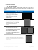
2.1.1.2. Range Finder
The Range Finder positioned in the center of the optical head measures the distance of the optical head
from the imaging target. The software user interface controlled by the HFC Display Screen (Section 6.2.1)
instructs the operator to move closer or move away from the imaging target to achieve optimal imaging
ranges. Refer to section 6.2.2.2.1 for full details on the Range Finder.
2.1.1.3. Ambient Light Sensor
The Ambient Light Sensor positioned in the bottom left corner of the HFC Optical Head measures the
ambient light level in the imaging environment. The software user interface (Section 6.2.2) controlled by
HFC Display Screen (Section 6.2.1) instructs the operator when correct ambient lighting conditions are
achieved for Fluorescence Imaging (Section 6.2.2.2.5). Refer to Section 6.2.2.2.5.1 for full details on the
Ambient Light Sensor.
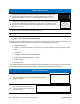
2.1.1.4. Temperature Sensor
The temperature sensor continually monitors the temperature of the optical head, ensuring the HFC does
not overheat and its operating parameters continually remain in tolerance. During imaging (Section
6.2.2.2) the Software User Interface (Section 6.2.2) controlled by the HFC Display Screen (Section 6.2.1)
displays a temperature gauge to communicate device temperature to the operator. Refer to section
6.2.2.2.1 for full details on the temperature gauge.
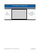
Figure 7 HFC Optical Head