
Manual

ASSEMBLY
2-15
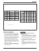
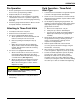
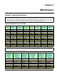
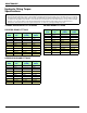
Figure 2-10: Harness Wire Designations
Electrical Installation
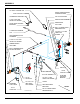
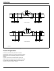
1. Attach left and right light brackets with reflectors to
frame using warning light bar, 1/2-13 x 7-1/2” hex
head cap screws and lock nuts. (See Figure 2-9)
2. Attach Amber LED lamps to light brackets using
1/4-20 x 1-1/4” hex head cap screws and lock nuts.
3. Attach left tail light mount to frame assembly using
U-bolt and 5/8-11 flange head serrated nuts.
4. Attach right tail light mount and flasher control
module to frame assembly using U-bolt and 5/8-11
flange head serrated nuts. Be sure that the control
module is set so that the 4 pin connector faces the
right side of the machine.
5. Attach reflector assemblies and Red LED lamps to
tail light mounts using 1/4-20 x 1-1/2” hex head cap
screws and lock nuts.
IMPORTANT
Make sure lights are positioned for maximum
visibility from the rear.
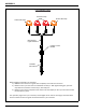
6. Install the LED warning light harness to the frame.
Connect 2 pin and 3 pin ends to each of the warning
lights. Connect 6 pin to the flasher control module.
7. Attach 7 pin/4pin 120” harness to frame. Connect 4
pin end to the flasher control module.
8. Insure that the harnesses are clear of any moving
parts and secure the harnesses with tie wraps
provided.
9. Install the stor-away holder bracket on the bolt in
coulter clamp plate and assemble harness stor-away
to the bracket with 1/4-20 x 3/4” hex head cap screws
and lock nuts.
7-PIN
CONN
1
2
3
4
5
6
7
D
B
A
C
GROUND
WORK LAMPS
LEFT FLASHING
& TURN
STOP LAMPS
RIGHT FLASHING
& TURN
TAIL LAMPS
SWITCHED
POWER (12V)
4-PIN
TOWER
GROUND
BLACK
YELLOW
RED
GREEN
BROWN
BLUE
CIRCUIT WIRE
COLOR
BLACK
LEFT TURN
WHITE
GROUND
BROWN
TAIL
YELLOW
LEFT TURN
GREEN
RIGHT
RED
RIGHT
A
B
C
D
E
F
2-PIN
TOWER
12345
3-PIN
TOWER
6-PIN
SHROUD
3-PIN
TOWER
2-PIN
TOWER
A
B
A
B
C
C
A
B
A
B
m2510 harness wire designations
7 PIN/4 PIN 120” HARNESS
LED WARNING LIGHT HARNESS