Zone Commander 2510 Operator’s Manual LANDOLL CORPORATION 1900 North Street Marysville, Kansas 66508 (785) 562-5381 800-428-5655 ~ WWW.LANDOLL.
Table of Contents 1 Introduction and Safety Information Using this Manual . . . . . . . . . . . . . . . . . . . . . . . . . . . . . . . . . . . . . . . . . . . . . . . . . . . . . . . . . . . . . 1-1 Owner Assistance . . . . . . . . . . . . . . . . . . . . . . . . . . . . . . . . . . . . . . . . . . . . . . . . . . . . . . . . . . . . . 1-1 Warranty Registration . . . . . . . . . . . . . . . . . . . . . . . . . . . . . . . . . . . . . . . . . . . . . . . . . . . . . . . . . .
Wheel Bearing Maintenance . . . . . . . . . . . . . . . . . . . . . . . . . . . . . . . . . . . . . . . . . . . . . . . . . . . . . 4-3 Coulter Spring Adjustment . . . . . . . . . . . . . . . . . . . . . . . . . . . . . . . . . . . . . . . . . . . . . . . . . . . . . . 4-3 Lubrication . . . . . . . . . . . . . . . . . . . . . . . . . . . . . . . . . . . . . . . . . . . . . . . . . . . . . . . . . . . . . . . . . . . 4-3 Storage . . . . . . . . . . . . . . . . . . . . . . . . . . . . . . . . . . . . . . . .
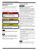
Chapter 1 Introduction and Safety Information The implement described in this manual has been designed with care and built by skilled workers using quality materials and processes. Proper assembly and maintenance will provide you with satisfactory use for seasons to come. DANGER Read this entire manual before attempting to assemble, adjust or operate this implement.
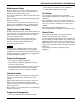
INTRODUCTION AND SAFETY INFORMATION Understanding Safety Statements You will find various types of safety information on the following pages and on the machine signs (decals) attached to the vehicle. This section explains their meaning. The Safety Alert Symbol means ATTENTION! YOUR SAFETY IS INVOLVED! DANGER Danger means a life-threatening situation exists. Death can occur if safety measures or instructions on this label are not properly followed.
INTRODUCTION AND SAFETY INFORMATION Maintenance Safety Block the machine so it will not roll when working on or under it to prevent injury in case of hydraulic failure or inadvertent lowering by another person. Do not make adjustments or lubricate the machine while it is in motion. Make sure all moving parts have stopped and all system pressure is relieved. Understand the procedure before doing the work. Use proper tools and equipment.
INTRODUCTION AND SAFETY INFORMATION Table provided for general use.
Chapter 2 Assembly It is very important that your new Zone Commander be properly assembled, adjusted, and lubricated before use. Illustrations are provided in this section to show proper assembly procedures. Remove paint from grease fittings and replace any that are damaged or missing. Be sure to return bolts, clips, etc. to their original locations. To insure assemblies are aligned, insert all bolts and leave the nuts loose until completion of final assembly.
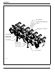
ASSEMBLY SMV EMBLEM SMV MOUNTING BRACKET U-BOLT 5/8-11 LOCK NUT 3/16 HAIRPIN OUTER JACK STAND TUBE JACK STAND OUTER JACK STAND TUBE JACK STAND 3/16 HAIR PIN PARTS ID Figure 2-1: Zone Commander 2510 Parts Identification 2-2 F-758-R0
ASSEMBLY Assembly Preparation SMV Bracket Installation 1. Hook up the Zone Commander to a tractor using the three-point hitch. Raise the unit about 36” and place stands under the main frame to prevent accidental lowering. 1. Attach the SMV mounting bracket to the center of the rear frame using U-bolt and 5/8-11 flange head serrated nuts. (See Figure 2-1) WARNING Do not attempt to lift heavy parts (such as the frame), manually. Use a hoist or a forklift to move these parts into position.
ASSEMBLY 5/8-11 X 3-3/4” HEX HEAD CAP SCREW 3/4-10 X 4” HEX HEAD CAP SCREW SPRING CLAMP ASSEMBLY PLACE PINS WITH ENDS OPPOSITE EACH OTHER CONNEX BUSHING 3/4-10 X 4” HEX HEAD CAP SCREW 3/4-10 LOCK NUT 5/8-11 LOCK NUT 3/4-10 LOCK NUT WEARSTRIP BRACKET 5/8-11 LOCK NUT SHANK POINT ASSEMBLY SEE DETAIL A WEARSTRIP STEEL POINT 3/4-10 X 3” HEX HEAD CAP SCREW 5/8-11 X 3-3/4” HEX HEAD CAP SCREW 1/2 X 2” SPRING SLOTTED PIN 5/16 X 2” SPRING SLOTTED PIN DETAIL A 1-1/4 AR Figure 2-2: Auto-Reset Clamp and Sha
ASSEMBLY 5/8-11 X 3-3/4” HEX HEAD CAP SCREW 3/4-10 X 4” HEX HEAD CAP SCREW SPRING CLAMP ASSEMBLY PLACE PINS WITH ENDS OPPOSITE EACH OTHER CONNEX BUSHING 3/4-10 X 4” HEX HEAD CAP SCREW 3/4-10 LOCK NUT 5/8-11 LOCK NUT 3/4-10 LOCK NUT WEARSTRIP BRACKET 5/8-11 LOCK NUT SHANK POINT ASSEMBLY SEE DETAIL A WEARSTRIP STEEL POINT 3/4-10 X 3” HEX HEAD CAP SCREW 5/8-11 X 3-3/4” HEX HEAD CAP SCREW 1/2 X 2” SPRING SLOTTED PIN 5/16 X 2” SPRING SLOTTED PIN 3/4 AR DETAIL A Figure 2-3: Auto-Reset Clamp and 3/4 S
ASSEMBLY CLAMP ASSEMBLY 3/4-10 LOCK NUT 5/8-11 LOCK NUT 3/4-10 X 4” HEX HEAD CAP SCREW 5/8-11 X 3-3/4” HEX HEAD CAP SCREW 1-1/4 X 4” BOLT-IN SHANK CONNEX BUSHING 1-1/4” SHARK FIN POINT 1-1/4” WINGED SUBSOILER POINT 3/8 X 2” SPRING SLOTTED PIN 1-1/4” SHANK V-CAP POINT 2410 shank inst op Figure 2-4: Auto-Reset Clamp and Shank Assembly 2-6 F-758-R0
ASSEMBLY Auto-Reset Clamp and Shank Assembly 1. The spring clamp weldments are already located on the frame at the proper spacing. 2. Attach wearstrip to straight leg shank using wearstrip bracket, 3/4-10 x 3” hex head cap screw, and 3/4-10 lock nut. (See Figures 2-2 through 2-4) 3. Attach steel point to straight leg shank using 1/2 x 2” and 5/16 x 2” spring slotted pins. Place pins with open ends oriented opposite of each other. 4.
ASSEMBLY 5/8-11 X 5-1/2” HEX HEAD CAP SCREW 3/4-10 X 4” HEX HEAD CAP SCREW PLACE PINS WITH ENDS OPPOSITE EACH OTHER RIGID CLAMP ASSEMBLY CONNEX BUSHING 3/4-10 LOCK NUT 5/8-11 LOCK NUT 3/4-10 X 4” HEX HEAD CAP SCREW 3/4-10 LOCK NUT 5/8-11 LOCK NUT SHANK POINT ASSEMBLY WEARSTRIP BRACKET WEARSTRIP SEE DETAIL A 3/4-10 X 3” HEX HEAD CAP SCREW 5/8-11 X 5-1/2” HEX HEAD CAP SCREW ½ X 2” SPRING SLOTTED PIN 5/16 X 2” SPRING SLOTTED PIN DETAIL A m179965 op Figure 2-5: RSB Clamp and Straight Shank Assembl
ASSEMBLY 5/8-11 X 5-1/2” HEX HEAD CAP SCREW 3/4-10 X 4” HEX HEAD CAP SCREW PLACE PINS WITH ENDS OPPOSITE EACH OTHER RIGID CLAMP ASSEMBLY CONNEX BUSHING 3/4-10 X 4” HEX HEAD CAP SCREW 3/4-10 LOCK NUT 5/8-11 LOCK NUT 3/4-10 LOCK NUT WEARSTRIP BRACKET 5/8-11 LOCK NUT SHANK POINT ASSEMBLY WEARSTRIP 3/4-10 X 3” HEX HEAD CAP SCREW 5/8-11 X 5-1/2” HEX HEAD CAP SCREW SEE DETAIL A ½ X 2” SPRING SLOTTED PIN 5/16 X 2” SPRING SLOTTED PIN DETAIL A m179965 op Figure 2-6: RSB Clamp and 3/4 Shank Assembly 2-
ASSEMBLY CLAMP ASSEMBLY 3/4-10 LOCK NUT 5/8-11 LOCK NUT 5/8-11 X 3-3/4” HEX HEAD CAP SCREW 3/4-10 HEX HEAD CAP SCREW CONNEX BUSHING 3/8 X 2” SPRING SLOTTED PIN 1-1/4” SHARK FIN POINT 1-1/4” WINGED SUBSOILER POINT 1-1/4” SHANK V-CAP POINT rigid parabolic Figure 2-7: RSB Clamp and Shank Assembly 2-10 F-758-R0
ASSEMBLY RSB Clamp and Straight Shank Assembly 1. The rigid clamp assemblies are already located on the frame at the proper spacing. 2. Attach wearstrip to straight leg shank using wearstrip bracket, 3/4-10 x 3” hex head cap screw, and 3/4-10 lock nut. (See Figures 2-5 through 2-7) 4. Attach top of shank point assembly to front of spring clamp assembly using 3/4-10 x 4” hex head cap screw and lock nut.
ASSEMBLY COULTER ADJUSTMENT TUBE 3/16” HAIR PIN ADJUSTMENT PIN ½ X 4” ROLL PIN U-BOLT 5/16 X 4” ROLL PIN CLAMP PLATE COULTER CLAMP TUBE ½ x 1-1/2” SCREW COULTER STOP ½ X 4” SCREW COULTER ASSEMBLY 5/8 LOCK NUT Figure 2-8: Coulter Assembly 2-12 F-758-R0
ASSEMBLY Coulter Assembly 1. Assemble the coulter adjustment tube to coulter assembly using roll pins 1/2 x 4’ and 5/16 x 4”. Assemble the coulter stop to the coulter adjustment tube using 1/2 x 4” screw and nut. (See Figure 2-8) 2. Install the coulter adjustment tube and coulter assembly to the frame using the coulter clamp tube, 4 U-bolts, clamp plate and 5/8 lock nuts. Do not tighten nuts until the depth adjustment is completed. 3. Use adjustment pin and 3/16 hairpin to set desired depth.
ASSEMBLY 19” SELF LOCKING TIE RIGHT HAND BRACKET W/ REFLECTORS 1/4-20 LOCK NUT HARNESS STOR-AWAY TAIL LIGHT MOUNT 1/4-20 X 3/4” HEX HEAD CAP SCREW REFLECTOR ASSEMBLY RED SINGLE LED LAMP STOR-AWAY HOLDER BRACKET 5/8-11 FLANGE HEAD SERRATED NUT 7 PIN/4 PIN HARNESS, 120” 1/4-20 X 1-1/2” HEX HEAD CAP SCREW LED WARNING LIGHT HARNESS 1/4-20 X 1-1/4” HEX HEAD CAP SCREW AMBER SINGLE LED LAMP LEFT HAND BRACKET W/ REFLECTORS U-BOLT SMV EMBLEM 1/4” FLAT WASHER WARNING LIGHT BAR 1/4-20 LOCK NUT 1/4-20 X 1”
ASSEMBLY 7-PIN 4-PIN CONN TOWER 1 2 3 4 5 6 7 D B A C CIRCUIT 1 WIRE COLOR GROUND WORK LAMPS LEFT FLASHING & TURN STOP LAMPS RIGHT FLASHING & TURN TAIL LAMPS SWITCHED POWER (12V) GROUND BLACK YELLOW RED GREEN BROWN BLUE 7 PIN/4 PIN 120” HARNESS 2 3 4 5 2-PIN 3-PIN 6-PIN 3-PIN 2-PIN TOWER TOWERSHROUDTOWER TOWER BLACK LEFT TURN WHITE GROUND BROWN TAIL YELLOW LEFT TURN GREEN RIGHT RED RIGHT A A C A B A B C B D B A B E C F LED WARNING LIGHT HARNESS m2510 harness wire designations
ASSEMBLY LED Warning Lights Red LED Lamp Amber LED Lamp Amber LED Lamp LED Warning Lights Harness Flasher Control Module 7Pin/4Pin WP Harness When plugging in the LED 7-pin connector: 1) Make sure the tractor has a good clean receptacle, free of dirt and corrosion. 2) Make sure the 7-pin connector is inserted ALL the way in. With tighter fitting pins, operator may think the connector is all the way in, but really isn’t.
Chapter 3 Operation DANGER Coulter blades are sharp. Do not allow coulters to roll over or fall on any part of the body. Do not allow wrenches to slip when working near coulter blades. Do not climb over machine above coulter blades. Failure to stay clear of coulter blade edges may result in serious personal injury or death. DANGER Never allow anyone to ride on the Zone Commander at any time.
OPERATION CAT II HITCH CAT III HITCH m2510-hitch Figure 3-1: 3 Point Hitch Setup Tractor Preparation The Zone Commander may be used on tractors equipped with category II or III three-point hitches. Before attaching the Zone Commander, prepare the tractor as follows: The rear tractor tires should be inflated equally and ballast added according to the tractor operator’s manual. For mounted type models, install front end weights as needed on tractor to maintain stability.
OPERATION Pre-Operation 1. Before operating the Zone Commander inspect it to be sure it is in good operating condition. Field Operation - Three-Point Hitch Type 2. Replace badly worn or missing parts. 1. Lower the Zone Commander to the ground and pull it a few feet at the approximate desired depth. 3. While the machine is new, bolt tightness should be checked after a few hours of operation. Tighten any loose nuts or cap screws. Check the gauge wheel lug bolts daily. 2.
OPERATION Table provided for general use.
Chapter 4 Maintenance General Torque Specifications This chart provides tightening torques for general purpose applications when special torques are not specified on process or drawing. Assembly torques apply to plated nuts and capscrews assembled without supplemental lubrication (as received condition). They do not apply if special graphite moly-disulfide or other extreme pressure lubricants are used. When fasteners are dry (solvent cleaned) add 33% to as received condition torque.
MAINTENANCE Hydraulic Fitting Torque Specifications 37 degree JIC, ORS, &ORB (REV. 10/97) This chart provides tightening torques for general purpose applications when special torques are not specified on process or drawing. Assembly torques apply to plated nuts and capscrews assembled without supplemental lubrication (as received condition). They do not apply if special graphite moly-disulfide or other extreme pressure lubricants are used.
MAINTENANCE Wheel Bearing Maintenance 1. Check wheel bearings and coulter bearings occasionally for excessive end play. To correctly replace the wheel bearings: 2. Place the frame on blocks or stands sufficient to lift the tire clear of the ground. Lubrication IMPORTANT Items with grease fittings are listed in the illustrated parts book. 4. Remove the hub. Clean and inspect the bearings and hub cavity. Replace any worn or defective parts. 1.
MAINTENANCE Trouble Shooting The Troubleshooting Guide, shown below, is included to help you quickly locate problems that can happen using your Zone Commander. Follow all safety precautions stated in the previous sections when making any adjustments to your machine.
Chapter 5 General Reference and Specifications Specifications ZONE COMMANDER SPECIFICATIONS MODEL NO. NO. OF SHANKS 2510-4-30 2510-5-30 2510-6-30 2510-7-30 4 5 6 7 SHANK SPACING 30” 30” 30” 30” FRAME EXTENSIONS NONE NONE 17” BOLT-ON 27” BOLT-ON TRANSPORT WIDTH 11’-6” 11’-6” 14’-3” 15’-10” ESTIMATED WEIGHT (LBS.) 3,205 3,812 4,610 5,162 TIRE INFLATION TIRE SIZE TIRE MANUFACTURER 20.5 x 8.0-10 PLY/LOAD RATING INFLATION PRESSURE (psi) (max.) Load Range D/ 1,320 lb.
GENERAL REFERENCE AND SPECIFICATIONS 40” 30” 30” 36” 50” 2510-3-30 Figure 5-1: 2510-3-30 Shank and Lighting Placement 5-2 F-758-R0
GENERAL REFERENCE AND SPECIFICATIONS 62-3/4” 51” 15” 15” 30” 27” 2510-4-30 Figure 5-2: 2510-4-30 Shank and Lighting Placement 5-3
GENERAL REFERENCE AND SPECIFICATIONS 62-3/4” 50” 30” 30” 42” 2510-5-30 Figure 5-3: 2510-5-30 Shank and Lighting Placement 5-4 F-758-R0
GENERAL REFERENCE AND SPECIFICATIONS 51” 27” 15” 30” 80-1/2” 2510-6-30 Figure 5-4: 2510-6-30 Shank and Lighting Placement 5-5
GENERAL REFERENCE AND SPECIFICATIONS 50” 30” 30” 42” 80-1/2” 2510--30 Figure 5-5: 2510-7-30 Shank and Lighting Placement 5-6 F-758-R0
Equipment from Landoll Corporation is built to exacting standards ensured by ISO 9001:2008 registration at all Landoll manufacturing facilities. Zone Commander 2510 Operator’s Manual Re-Order Part Number F-758-R0 LANDOLL CORPORATION 1900 North Street Marysville, Kansas 66508 (785) 562-5381 800-428-5655 ~ WWW.LANDOLL.COM Copyright 2014. Landoll Corporation "All rights reserved, including the right to reproduce this material or portions thereof in any form.