
2131 Wing Coulter Chisel User Manual


OPERATION AND MAINTENANCE
4-13
Hydraulic Maintenance
1. Check the tractor hydraulic fluid level per tractor
owners manual and after any leakage. Check fluid
level with the cylinders in the retracted position.
2. If a cylinder or valve leaks, dis assemble the parts to
determine the cause of the leak. Any time a cylinder
is opened up, or whenever any seal replacement is
necessary, it is advisable to clean all parts and
replace all seals. Seal kits are available from your
Landoll dealer.
3. Check all hydraulic ho ses weekly. Look for binding or
cracking. Replace all worn or defective pa rts
immediately.
IMPORTANT
Lower the unit to th e ground, and relieve hydraulic
pressure before attempting to service any hydraulic
component.
4. T ransport locks are pro vided to hold the implement in
a raised position. Do not attempt to perform any
service work unde r the imp le me n t with ou t first
installing the transport locks. Before servicing any
hydraulic component, lower the implement to the
ground and relieve all system pressure . If a hydraulic
component is disconnected, repair ed, or replaced, it
will be necessary to purge the system of air before
operation. See “Hydraulic Lift System” on
page 4-2 and “Hydraulic Fold System” on
page 4-4 on how to purge the hydraulic systems.
Transport
1. Check and follow all federal, state, and local
requirements before transporting the Coulter Chisel.
2. The 2131 Wing Coulter Chisel should be tr ansporte d
only by tractor required for field operation. The
implement weight should not exceed more than 1.5
times the tractor weight. Unless noted on the
implement, maximum transport speed is 20 mph for
the implement. Slow down when driving on rough
roads. Reduce speed when turning, or on curves and
slopes to avoid tipping.
3. A safety chain is provide d with the implement to
insure safe transport.
a. The safety chain should have a tensile strength
equal to or greater than the gross weight of the
implement. The chain is attached to the lower
hitch clevis hole with two flat washers between
the clamp plates to assure a tight connection.
Always use a 1” diameter Grade 8 bolt for this
connection.
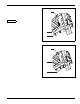
b. Att ach the safety chain to the tractor drawbar
(See Figure 4-12.) Provide only enough slack in
the chain for turning. Do no t use an intermediate
chain support as the att achi ng point for the chain
on the tractor. Do not pull the implement by the
safety chain.
c. When unhitching from the tractor att ach the hook
end of the chain to a free link close to the hitch
clevis for storage. This will keep the hook off the
ground, reducing co rrosion and keep the hook
functioning properly.
d. Regularly inspect the safety chain for worn,
stretched, or broken links and e nds. Replace the
safety chain if it is damaged or deformed in any
way.
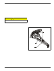
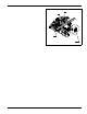
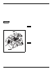
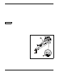
Figure 4-12: Hitch, Speed Identification Symbol,
and Safety Cha in
HITCH WELDMENT
SAFETY
CHAIN
SPEED
IDENTIFICATION SYMBOL
2110 hitch adj