
2131 Wing Coulter Chisel User Manual


3-6 F-721-0513 Edition
ASSEMBLY INSTRUCTIONS
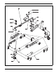
Depth Stop Tube Assembly
1. Attach the depth stop mount plate to the shank lift
using 3/8-16 x 1-1/4 hex head cap screws and hex
lock nuts.
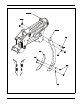
2. Lay the depth stop tube assembly on top of the
center frame. Insert a 5/8- 11 x 2-1/2 hex head cap
screw in the rear hole of the tube assembly from the
left side (See Figure 3-3.) Install a 5/8-11 hex lock
nut on the screw. Do not over tighten, as th e de pth
stop must pivot on this screw.
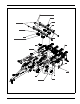
3. Insert 90
o
elbow fittings in the back of the limit valve
and a straight adapter in the side nearest the center
of the machine.
4. Using 5/16-18 x 5 hex head cap screws secure the
front end of the depth stop tube assembly to the top
of the frame mount with the depth stop guide, slide
pad, and 5/16-18 hex lock nu ts. Attach the limit valve
to the bottom side of the center frame mount using
these same scre ws .
IMPORTANT
It may be necessary to leave these screws loose to
attach the valve hoses later.