
Manual


ASSEMBLY INSTRUCTIONS
3-29
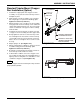
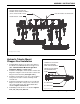
Standard Tubular Mount Chopper
Reel Installation (Option)
1. Install 2 hole support plate into chopper reel arm
assembly. Use (2) 3/4-10 x 3 hex head cap screws to
hold plate in place.
2. Slide chopper reel arm assemblies over rear frame
bar using chopper reel placement drawings (See
Figures 2-11 thru 2-15, and 3-21.)
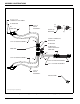
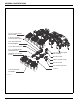
3. Attach top plate to top of chopper reel arm assembly
using (4) 3/4-10 x 13 hex head cap screws. Slide arm
support tube and bottom plate onto 13” hex head cap
screws on underside of chopper reel arm assembly
and rear frame.
4. Install 3/4-10 x 2 hex head cap screw into front side
of chopper reel arm assembly, and arm support tube.
5. Evenly tighten the 3/4-10 x 13 hex head cap screws
first. Then tighten the front 3/4-10 x 2 hex head cap
screw. Tighten 3/4-10 x 3 hex head cap screws last,
but be sure to not overtighten. These screws need to
be snug.
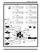
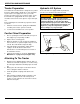
6. Adjust spring to 21” (See Figure 3-23.)
7. Attach reel/gang bar assemblies to chopper reel arm
assemblies using placement drawings (See
Figures 2-11 thru 2-15, and 3-21.)
8. Bolt in place using gang bar mount plate, 3/4-10 x 6
hex head cap screws, and hex lock nuts.
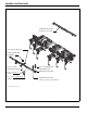
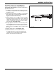
9. If unfavorable conditions exist or the chopper reel is
not needed, the arm can be raised and pinned into a
higher position creating little or no disturbance of the
soil with the chopper reel (See Figure 3-22.)
NOTE
Hydraulic chopper reels do not have pins. They are held
up by hydraulic cylinders.
Figure 3-22: Unused Chopper Reel Position
Figure 3-23: Spring Adjustment
NORMAL OPERATING/
STORAGE POSITION
PINNED UP POSITION
(WHEN CHOPPER REEL
NOT REQUIRED)
3/16 HAIR PIN
1/4 X 2-1/2
SLOTTED
ROLL PIN
PIN
unused chopper reel position
21”
spring adjustment