
User Manual

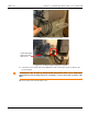

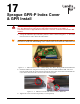

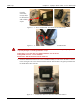

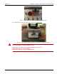


Table Of Contents
- 13-0144 - Exhibit Cover.pdf
- 98-1135 installation manual.pdf
- Chapter 1: Pre-Installation 7
- Chapter 2: American Index Cover & Gas Module Removal 23
- Chapter 3: Rockwell Index Cover & Gas Module Removal 27
- Chapter 4: Schlumberger Index Cover & Gas Module Removal 31
- Chapter 5: Sprague Index Cover & Gas Module Removal 35
- Chapter 6: American Mini Switch Kit Installation 39
- Chapter 7: Rockwell Mini Switch Kit Installation 47
- Chapter 8: Schlumberger Mini Switch Kit Installation 51
- Chapter 9: Sprague Mini Switch Kit Installation 55
- Chapter 10: American GPR Configuration and Waterproofing 61
- Chapter 11: Rockwell GPR Configuration and Waterproofing 67
- Chapter 12: Schlumberger GPR Config & Waterproofing 73
- Chapter 13: Sprague GPR Configuration and Waterproofing 77
- Chapter 14: American GPR-P Index Cover & GPR Install 81
- Chapter 15: Rockwell GPR-P Index Cover & GPR Install 85
- Chapter 16: Schlumberger GPR-P Index Cover & GPR Install 89
- Chapter 17: Sprague GPR-P Index Cover & GPR Install 93
- Appendix A: American Changing GPR Orientation 99
- Appendix B: Rockwell Changing GPR Orientation 103
- Appendix C: Schlumberger Changing GPR Orientation 105
- Appendix D: Sprague Changing GPR Direction 107
- Appendix E: GPR Connection Water Proofing Materials 111
- Table 1-1. Typical Gas Meter Module Installation Tool List
- Table 1-2. American Large Diaphragm Meter Mini Switch Kits
- Table 1-3. American Large Diaphragm Meter Dial Wheels
- Table 1-4. Kit, GPR Installation, American Large Diaphragm, Right Bracket #45-1189
- Table 1-5. Kit, GPR Installation, American Large Diaphragm, Behind Index #45-1190
- Table 1-6. Kit, American Large Diaphragm Left Bracket GPR, #45-1193
- Table 1-7. Hardware Kit, American Large Diaphragm #45-1203
- Table 1-8. GPR With Universal Mounting Bracket and Hardware #45-1185
- Table 1-9. GPR Cover Mounting Kit #45-1042
- Table 1-10. Rockwell Large Diaphragm Meter Solid State Pulser Kit
- Table 1-11. Rockwell Large Diaphragm Meter Solid State Pulser Two-Piece Dial Wheel
- Table 1-12. Complete GPR Installation Kit for Rockwell 750 Large Diaphragm Meter #45-1186
- Table 1-13. Kit, Rockwell Large Diaphragm Index Cover Hardware #45-1169
- Table 1-14. GPR Kit with Universal Mounting Bracket and Hardware #45-1178
- Table 1-15. Schlumberger Large Diaphragm Meter Solid State Pulser Kit
- Table 1-16. Schlumberger Large Diaphragm Meter Solid State Pulser Two-Piece Dial Wheel
- Table 1-17. Schlumberger Large Diaphragm GPR Kit #45-1187
- Table 1-18. Kit, Schlumberger Large Diaphragm Index Cover Hardware # 45-1171
- Table 1-19. GPR Kit with Universal Mounting Bracket and Hardware #45-1178
- Table 1-20. Sprague Large Diaphragm Meter Solid State Pulser Kit
- Table 1-21. GPR-P Dial Wheels
- Table 1-22. Complete GPR Installation Kit for Sprague 675 - 1000 Meters #45-1188
- Table 1-23. Sprague Large Diaphragm Index Cover Hardware Kit #45-1114
- Table 1-24. GPR Kit with Universal Mounting Bracket and Hardware #45-1178

Landis+Gyr Chapter 17 - Sprague GPR-P Index Cover & GPR Install
Installation Guide 98-1135 Rev AA 95
Figure 17 - 5. Excess Coiled Cable Attached Beneath GPR Bracket
Figure 17 - 6. Excess Coiled Cable Attached Beneath GPR Bracket
U WARNING: Take care not to pinch the index cover switch cable assembly in any way,
especially during the following installation steps:
During index cover and cable assembly installation onto the meter.
During GPR enclosure cover installation.
Between the GPR and meter brackets and meter.
7. Install the Solid State Pulser index cover and GPR assembly over the meter dial index as shown
in the next figure. The cover must be installed with the 1/8 inch thick cork gasket provided with
the Solid State Pulser index kit.
Figure 17 - 7. Switch Wires Must Not Interfere With Index Pointers
Loosely
secure the
excess cable
to the bracket
with a black
zip tie