
User Manual

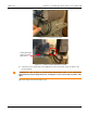

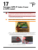

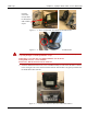

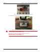


Table Of Contents
- 13-0144 - Exhibit Cover.pdf
- 98-1135 installation manual.pdf
- Chapter 1: Pre-Installation 7
- Chapter 2: American Index Cover & Gas Module Removal 23
- Chapter 3: Rockwell Index Cover & Gas Module Removal 27
- Chapter 4: Schlumberger Index Cover & Gas Module Removal 31
- Chapter 5: Sprague Index Cover & Gas Module Removal 35
- Chapter 6: American Mini Switch Kit Installation 39
- Chapter 7: Rockwell Mini Switch Kit Installation 47
- Chapter 8: Schlumberger Mini Switch Kit Installation 51
- Chapter 9: Sprague Mini Switch Kit Installation 55
- Chapter 10: American GPR Configuration and Waterproofing 61
- Chapter 11: Rockwell GPR Configuration and Waterproofing 67
- Chapter 12: Schlumberger GPR Config & Waterproofing 73
- Chapter 13: Sprague GPR Configuration and Waterproofing 77
- Chapter 14: American GPR-P Index Cover & GPR Install 81
- Chapter 15: Rockwell GPR-P Index Cover & GPR Install 85
- Chapter 16: Schlumberger GPR-P Index Cover & GPR Install 89
- Chapter 17: Sprague GPR-P Index Cover & GPR Install 93
- Appendix A: American Changing GPR Orientation 99
- Appendix B: Rockwell Changing GPR Orientation 103
- Appendix C: Schlumberger Changing GPR Orientation 105
- Appendix D: Sprague Changing GPR Direction 107
- Appendix E: GPR Connection Water Proofing Materials 111
- Table 1-1. Typical Gas Meter Module Installation Tool List
- Table 1-2. American Large Diaphragm Meter Mini Switch Kits
- Table 1-3. American Large Diaphragm Meter Dial Wheels
- Table 1-4. Kit, GPR Installation, American Large Diaphragm, Right Bracket #45-1189
- Table 1-5. Kit, GPR Installation, American Large Diaphragm, Behind Index #45-1190
- Table 1-6. Kit, American Large Diaphragm Left Bracket GPR, #45-1193
- Table 1-7. Hardware Kit, American Large Diaphragm #45-1203
- Table 1-8. GPR With Universal Mounting Bracket and Hardware #45-1185
- Table 1-9. GPR Cover Mounting Kit #45-1042
- Table 1-10. Rockwell Large Diaphragm Meter Solid State Pulser Kit
- Table 1-11. Rockwell Large Diaphragm Meter Solid State Pulser Two-Piece Dial Wheel
- Table 1-12. Complete GPR Installation Kit for Rockwell 750 Large Diaphragm Meter #45-1186
- Table 1-13. Kit, Rockwell Large Diaphragm Index Cover Hardware #45-1169
- Table 1-14. GPR Kit with Universal Mounting Bracket and Hardware #45-1178
- Table 1-15. Schlumberger Large Diaphragm Meter Solid State Pulser Kit
- Table 1-16. Schlumberger Large Diaphragm Meter Solid State Pulser Two-Piece Dial Wheel
- Table 1-17. Schlumberger Large Diaphragm GPR Kit #45-1187
- Table 1-18. Kit, Schlumberger Large Diaphragm Index Cover Hardware # 45-1171
- Table 1-19. GPR Kit with Universal Mounting Bracket and Hardware #45-1178
- Table 1-20. Sprague Large Diaphragm Meter Solid State Pulser Kit
- Table 1-21. GPR-P Dial Wheels
- Table 1-22. Complete GPR Installation Kit for Sprague 675 - 1000 Meters #45-1188
- Table 1-23. Sprague Large Diaphragm Index Cover Hardware Kit #45-1114
- Table 1-24. GPR Kit with Universal Mounting Bracket and Hardware #45-1178

Chapter 17 - Sprague GPR-P Index Cover & GPR Install Landis+Gyr
94 98-1135 Rev AA Installation Guide
U WARNING: The Index Cover Cable assembly must not be pinched during GPR cover
installation.
Figure 17 - 3. GPR Cover Security Torx Screws
4. Bend about three inches of cable into a loop and attach the cable to the bracket with a nylon zip
tie as shown in the following figure. Do not bend the cable so much as to crimp it. This provides
additional security for the cable and serves as a drip loop.
Figure 17 - 4. Switch Cover and GPR Assembly, with drip loop
NOTE: The cable strain relief is water tight and does not require a drip loop
5. Position the GPR bracket assembly over the cover edges as shown in Figure 17 - 4.
A CAUTION: Check the index cover switch cable assembly for nicks, abrasions, or any damage
prior to installing the assembly onto the meter.
6. Coil the excess cable and route it behind the bracket as shown in Figure 17 - 5. Position the cable
behind the bracket and secure the cable to the bracket immediately below the GPR housing with
a black nylon zip tie. Do not completely tighten the zip tie. The cable must remain free to move
until the GPR has been installed on the meter.