
User Manual


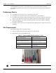

Table Of Contents
- 13-0144 - Exhibit Cover.pdf
- 98-1135 installation manual.pdf
- Chapter 1: Pre-Installation 7
- Chapter 2: American Index Cover & Gas Module Removal 23
- Chapter 3: Rockwell Index Cover & Gas Module Removal 27
- Chapter 4: Schlumberger Index Cover & Gas Module Removal 31
- Chapter 5: Sprague Index Cover & Gas Module Removal 35
- Chapter 6: American Mini Switch Kit Installation 39
- Chapter 7: Rockwell Mini Switch Kit Installation 47
- Chapter 8: Schlumberger Mini Switch Kit Installation 51
- Chapter 9: Sprague Mini Switch Kit Installation 55
- Chapter 10: American GPR Configuration and Waterproofing 61
- Chapter 11: Rockwell GPR Configuration and Waterproofing 67
- Chapter 12: Schlumberger GPR Config & Waterproofing 73
- Chapter 13: Sprague GPR Configuration and Waterproofing 77
- Chapter 14: American GPR-P Index Cover & GPR Install 81
- Chapter 15: Rockwell GPR-P Index Cover & GPR Install 85
- Chapter 16: Schlumberger GPR-P Index Cover & GPR Install 89
- Chapter 17: Sprague GPR-P Index Cover & GPR Install 93
- Appendix A: American Changing GPR Orientation 99
- Appendix B: Rockwell Changing GPR Orientation 103
- Appendix C: Schlumberger Changing GPR Orientation 105
- Appendix D: Sprague Changing GPR Direction 107
- Appendix E: GPR Connection Water Proofing Materials 111
- Table 1-1. Typical Gas Meter Module Installation Tool List
- Table 1-2. American Large Diaphragm Meter Mini Switch Kits
- Table 1-3. American Large Diaphragm Meter Dial Wheels
- Table 1-4. Kit, GPR Installation, American Large Diaphragm, Right Bracket #45-1189
- Table 1-5. Kit, GPR Installation, American Large Diaphragm, Behind Index #45-1190
- Table 1-6. Kit, American Large Diaphragm Left Bracket GPR, #45-1193
- Table 1-7. Hardware Kit, American Large Diaphragm #45-1203
- Table 1-8. GPR With Universal Mounting Bracket and Hardware #45-1185
- Table 1-9. GPR Cover Mounting Kit #45-1042
- Table 1-10. Rockwell Large Diaphragm Meter Solid State Pulser Kit
- Table 1-11. Rockwell Large Diaphragm Meter Solid State Pulser Two-Piece Dial Wheel
- Table 1-12. Complete GPR Installation Kit for Rockwell 750 Large Diaphragm Meter #45-1186
- Table 1-13. Kit, Rockwell Large Diaphragm Index Cover Hardware #45-1169
- Table 1-14. GPR Kit with Universal Mounting Bracket and Hardware #45-1178
- Table 1-15. Schlumberger Large Diaphragm Meter Solid State Pulser Kit
- Table 1-16. Schlumberger Large Diaphragm Meter Solid State Pulser Two-Piece Dial Wheel
- Table 1-17. Schlumberger Large Diaphragm GPR Kit #45-1187
- Table 1-18. Kit, Schlumberger Large Diaphragm Index Cover Hardware # 45-1171
- Table 1-19. GPR Kit with Universal Mounting Bracket and Hardware #45-1178
- Table 1-20. Sprague Large Diaphragm Meter Solid State Pulser Kit
- Table 1-21. GPR-P Dial Wheels
- Table 1-22. Complete GPR Installation Kit for Sprague 675 - 1000 Meters #45-1188
- Table 1-23. Sprague Large Diaphragm Index Cover Hardware Kit #45-1114
- Table 1-24. GPR Kit with Universal Mounting Bracket and Hardware #45-1178

Chapter 1 - Pre-Installation Landis+Gyr
8 98-1135 Rev AA Installation Guide
understand that their supervisor’s responsibility does not relieve them from their individual
responsibility to perform the work safely and to follow all safety rules and procedures applicable to
their work.
Preliminary Checks
1. The installer will verify correct site, as specified on work order.
2. The installer will verify that the site is safe for installer activity and equipment.
3. The installer will notify the customer of installer presence and activity, telling the customer that
meter access is required. If necessary, the installer will have the customer sign the work order.
4. When installing meters, the installer will follow guidelines issued by the utility in addition to
those given in this guide.
5. The installer will never perform an installation during a lightning storm or under excessively wet
conditions.
Site Requirements
The site must comply with the following criteria:
1. There is no chance that another object will be set over the antenna.
2. Some instances may require additional cable.
Figure 1 - 1. Examples of some required tools
NOTE:
Table 1-1. Typical Gas Meter Module Installation Tool List
Torx Pin Head Driver, T10 Phillips Screwdriver, #2
Flat-tip Screwdriver, 3/16 inch x 4 inch Flat-tip Screwdriver, 1/4 inch x 5 inch
Phillips Screwdriver, #0, precision
Torque Driver / Wrench, 0.5 inch-
pounds to 20 foot-pounds
Torx Pin Head Driver, T15 5/16 Combination Wrench
Wire Brush Awl, Heavy duty
Scraper, Brass, 1.25 inch wide