
User Manual


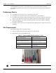

Table Of Contents
- 13-0144 - Exhibit Cover.pdf
- 98-1135 installation manual.pdf
- Chapter 1: Pre-Installation 7
- Chapter 2: American Index Cover & Gas Module Removal 23
- Chapter 3: Rockwell Index Cover & Gas Module Removal 27
- Chapter 4: Schlumberger Index Cover & Gas Module Removal 31
- Chapter 5: Sprague Index Cover & Gas Module Removal 35
- Chapter 6: American Mini Switch Kit Installation 39
- Chapter 7: Rockwell Mini Switch Kit Installation 47
- Chapter 8: Schlumberger Mini Switch Kit Installation 51
- Chapter 9: Sprague Mini Switch Kit Installation 55
- Chapter 10: American GPR Configuration and Waterproofing 61
- Chapter 11: Rockwell GPR Configuration and Waterproofing 67
- Chapter 12: Schlumberger GPR Config & Waterproofing 73
- Chapter 13: Sprague GPR Configuration and Waterproofing 77
- Chapter 14: American GPR-P Index Cover & GPR Install 81
- Chapter 15: Rockwell GPR-P Index Cover & GPR Install 85
- Chapter 16: Schlumberger GPR-P Index Cover & GPR Install 89
- Chapter 17: Sprague GPR-P Index Cover & GPR Install 93
- Appendix A: American Changing GPR Orientation 99
- Appendix B: Rockwell Changing GPR Orientation 103
- Appendix C: Schlumberger Changing GPR Orientation 105
- Appendix D: Sprague Changing GPR Direction 107
- Appendix E: GPR Connection Water Proofing Materials 111
- Table 1-1. Typical Gas Meter Module Installation Tool List
- Table 1-2. American Large Diaphragm Meter Mini Switch Kits
- Table 1-3. American Large Diaphragm Meter Dial Wheels
- Table 1-4. Kit, GPR Installation, American Large Diaphragm, Right Bracket #45-1189
- Table 1-5. Kit, GPR Installation, American Large Diaphragm, Behind Index #45-1190
- Table 1-6. Kit, American Large Diaphragm Left Bracket GPR, #45-1193
- Table 1-7. Hardware Kit, American Large Diaphragm #45-1203
- Table 1-8. GPR With Universal Mounting Bracket and Hardware #45-1185
- Table 1-9. GPR Cover Mounting Kit #45-1042
- Table 1-10. Rockwell Large Diaphragm Meter Solid State Pulser Kit
- Table 1-11. Rockwell Large Diaphragm Meter Solid State Pulser Two-Piece Dial Wheel
- Table 1-12. Complete GPR Installation Kit for Rockwell 750 Large Diaphragm Meter #45-1186
- Table 1-13. Kit, Rockwell Large Diaphragm Index Cover Hardware #45-1169
- Table 1-14. GPR Kit with Universal Mounting Bracket and Hardware #45-1178
- Table 1-15. Schlumberger Large Diaphragm Meter Solid State Pulser Kit
- Table 1-16. Schlumberger Large Diaphragm Meter Solid State Pulser Two-Piece Dial Wheel
- Table 1-17. Schlumberger Large Diaphragm GPR Kit #45-1187
- Table 1-18. Kit, Schlumberger Large Diaphragm Index Cover Hardware # 45-1171
- Table 1-19. GPR Kit with Universal Mounting Bracket and Hardware #45-1178
- Table 1-20. Sprague Large Diaphragm Meter Solid State Pulser Kit
- Table 1-21. GPR-P Dial Wheels
- Table 1-22. Complete GPR Installation Kit for Sprague 675 - 1000 Meters #45-1188
- Table 1-23. Sprague Large Diaphragm Index Cover Hardware Kit #45-1114
- Table 1-24. GPR Kit with Universal Mounting Bracket and Hardware #45-1178

1
Installation Guide 98-1135 Rev AA 7
Pre-Installation
Before You Begin
This text contains the symbols which are explained below.
NOTE: Notes provide important information about products and installation.
A CAUTION: Cautions provide information that you must read to avoid making relatively
moderate errors.
U WARNING: Warnings provide special, must-read information. If you ignore a warning you may
create a safety hazard, omit essential data, or make a critical error.
Safety Overview
NOTE: Proper planning and thorough preparation are critical for successful installation. This
chapter outlines basic requirements for the pre-installation phase.
Prior to starting the installation process, you must develop and launch an installer safety training
plan for initial, refresher, and ongoing safety training. Ensure that installers receive appropriate
initial and refresher training to meet their specific safety-related responsibilities. Installers should be
instructed in the following safety elements as well as any site-specific safety issues.
• New duties for which the installer has not previously received training.
• New processes and methodologies representing new risks that are introduced into the
installation environment.
• Situations where previously unidentified risks are reported.
• Hazard Communication (Employee Right to Know)
• Lifting
• Safe driving
• Use of hand tools
• Confined space
The installation supervisory team assumes responsibility for ensuring that installers are properly
trained, authorized, and continually qualified to perform their work. The team must also take
responsibility for the safety of their installers and to assure safe work methodologies. Installers must