
User Manual
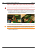
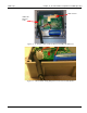


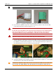
Table Of Contents
- 13-0144 - Exhibit Cover.pdf
- 98-1135 installation manual.pdf
- Chapter 1: Pre-Installation 7
- Chapter 2: American Index Cover & Gas Module Removal 23
- Chapter 3: Rockwell Index Cover & Gas Module Removal 27
- Chapter 4: Schlumberger Index Cover & Gas Module Removal 31
- Chapter 5: Sprague Index Cover & Gas Module Removal 35
- Chapter 6: American Mini Switch Kit Installation 39
- Chapter 7: Rockwell Mini Switch Kit Installation 47
- Chapter 8: Schlumberger Mini Switch Kit Installation 51
- Chapter 9: Sprague Mini Switch Kit Installation 55
- Chapter 10: American GPR Configuration and Waterproofing 61
- Chapter 11: Rockwell GPR Configuration and Waterproofing 67
- Chapter 12: Schlumberger GPR Config & Waterproofing 73
- Chapter 13: Sprague GPR Configuration and Waterproofing 77
- Chapter 14: American GPR-P Index Cover & GPR Install 81
- Chapter 15: Rockwell GPR-P Index Cover & GPR Install 85
- Chapter 16: Schlumberger GPR-P Index Cover & GPR Install 89
- Chapter 17: Sprague GPR-P Index Cover & GPR Install 93
- Appendix A: American Changing GPR Orientation 99
- Appendix B: Rockwell Changing GPR Orientation 103
- Appendix C: Schlumberger Changing GPR Orientation 105
- Appendix D: Sprague Changing GPR Direction 107
- Appendix E: GPR Connection Water Proofing Materials 111
- Table 1-1. Typical Gas Meter Module Installation Tool List
- Table 1-2. American Large Diaphragm Meter Mini Switch Kits
- Table 1-3. American Large Diaphragm Meter Dial Wheels
- Table 1-4. Kit, GPR Installation, American Large Diaphragm, Right Bracket #45-1189
- Table 1-5. Kit, GPR Installation, American Large Diaphragm, Behind Index #45-1190
- Table 1-6. Kit, American Large Diaphragm Left Bracket GPR, #45-1193
- Table 1-7. Hardware Kit, American Large Diaphragm #45-1203
- Table 1-8. GPR With Universal Mounting Bracket and Hardware #45-1185
- Table 1-9. GPR Cover Mounting Kit #45-1042
- Table 1-10. Rockwell Large Diaphragm Meter Solid State Pulser Kit
- Table 1-11. Rockwell Large Diaphragm Meter Solid State Pulser Two-Piece Dial Wheel
- Table 1-12. Complete GPR Installation Kit for Rockwell 750 Large Diaphragm Meter #45-1186
- Table 1-13. Kit, Rockwell Large Diaphragm Index Cover Hardware #45-1169
- Table 1-14. GPR Kit with Universal Mounting Bracket and Hardware #45-1178
- Table 1-15. Schlumberger Large Diaphragm Meter Solid State Pulser Kit
- Table 1-16. Schlumberger Large Diaphragm Meter Solid State Pulser Two-Piece Dial Wheel
- Table 1-17. Schlumberger Large Diaphragm GPR Kit #45-1187
- Table 1-18. Kit, Schlumberger Large Diaphragm Index Cover Hardware # 45-1171
- Table 1-19. GPR Kit with Universal Mounting Bracket and Hardware #45-1178
- Table 1-20. Sprague Large Diaphragm Meter Solid State Pulser Kit
- Table 1-21. GPR-P Dial Wheels
- Table 1-22. Complete GPR Installation Kit for Sprague 675 - 1000 Meters #45-1188
- Table 1-23. Sprague Large Diaphragm Index Cover Hardware Kit #45-1114
- Table 1-24. GPR Kit with Universal Mounting Bracket and Hardware #45-1178

Landis+Gyr Chapter 12 - Schlumberger GPR Config & Waterproofing
Installation Guide 98-1135 Rev AA 75
Figure 12 - 5. Apply the Compound to GPR Cable Connectors: Cover All Contacts
4. First, install the GPR Pulse Input cable, and then the Battery Interface cable, onto the GPR
circuit board connectors as shown in Figure 11 - 10.
U WARNING: The GPR Pulse Input cable MUST be installed prior to installing the Battery cable.
Do NOT disconnect the Battery cable after it has been installed. Disconnecting the battery
may cause unwanted pulses to be counted by the GPR. If the battery is disconnected,
reprogram the GPR to clear any unwanted pulse counts, then reconnect the battery.
U WARNING: Substitution of components may impair the suitability for Class I, Division 2
applications. Replace battery only with Landis+Gyr part number 40-1590H.
5. Liberally apply the compound to the back of each cable connector, forcing the compound into
each hole where the wires exit the connectors. The GPR circuit board and cable connectors must
be completely covered as shown in Figure 11 - 10. A cotton tipped swab may be used to force
the compound between each wire and into each connector hole.
Figure 12 - 6. The Compound Must Cover Wires and Connectors for Watertight Seal
6. Arrange the GPR Pulse Input and Battery Interface cables as shown in Figure 11 - 11. The cables
must not interfere with or block the GPR antenna.
A CAUTION: The GPR Pulse Input cable must be inserted into the GPR enclosure strain relief
slot as shown. The shrink tubing on the cable must be inserted into the strain relief slot.
7. Gently press the cable downward into the strain relief slot at midpoint of the heat shrink tubing
as shown in the following figures.