
User Manual


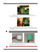
Table Of Contents
- 13-0144 - Exhibit Cover.pdf
- 98-1135 installation manual.pdf
- Chapter 1: Pre-Installation 7
- Chapter 2: American Index Cover & Gas Module Removal 23
- Chapter 3: Rockwell Index Cover & Gas Module Removal 27
- Chapter 4: Schlumberger Index Cover & Gas Module Removal 31
- Chapter 5: Sprague Index Cover & Gas Module Removal 35
- Chapter 6: American Mini Switch Kit Installation 39
- Chapter 7: Rockwell Mini Switch Kit Installation 47
- Chapter 8: Schlumberger Mini Switch Kit Installation 51
- Chapter 9: Sprague Mini Switch Kit Installation 55
- Chapter 10: American GPR Configuration and Waterproofing 61
- Chapter 11: Rockwell GPR Configuration and Waterproofing 67
- Chapter 12: Schlumberger GPR Config & Waterproofing 73
- Chapter 13: Sprague GPR Configuration and Waterproofing 77
- Chapter 14: American GPR-P Index Cover & GPR Install 81
- Chapter 15: Rockwell GPR-P Index Cover & GPR Install 85
- Chapter 16: Schlumberger GPR-P Index Cover & GPR Install 89
- Chapter 17: Sprague GPR-P Index Cover & GPR Install 93
- Appendix A: American Changing GPR Orientation 99
- Appendix B: Rockwell Changing GPR Orientation 103
- Appendix C: Schlumberger Changing GPR Orientation 105
- Appendix D: Sprague Changing GPR Direction 107
- Appendix E: GPR Connection Water Proofing Materials 111
- Table 1-1. Typical Gas Meter Module Installation Tool List
- Table 1-2. American Large Diaphragm Meter Mini Switch Kits
- Table 1-3. American Large Diaphragm Meter Dial Wheels
- Table 1-4. Kit, GPR Installation, American Large Diaphragm, Right Bracket #45-1189
- Table 1-5. Kit, GPR Installation, American Large Diaphragm, Behind Index #45-1190
- Table 1-6. Kit, American Large Diaphragm Left Bracket GPR, #45-1193
- Table 1-7. Hardware Kit, American Large Diaphragm #45-1203
- Table 1-8. GPR With Universal Mounting Bracket and Hardware #45-1185
- Table 1-9. GPR Cover Mounting Kit #45-1042
- Table 1-10. Rockwell Large Diaphragm Meter Solid State Pulser Kit
- Table 1-11. Rockwell Large Diaphragm Meter Solid State Pulser Two-Piece Dial Wheel
- Table 1-12. Complete GPR Installation Kit for Rockwell 750 Large Diaphragm Meter #45-1186
- Table 1-13. Kit, Rockwell Large Diaphragm Index Cover Hardware #45-1169
- Table 1-14. GPR Kit with Universal Mounting Bracket and Hardware #45-1178
- Table 1-15. Schlumberger Large Diaphragm Meter Solid State Pulser Kit
- Table 1-16. Schlumberger Large Diaphragm Meter Solid State Pulser Two-Piece Dial Wheel
- Table 1-17. Schlumberger Large Diaphragm GPR Kit #45-1187
- Table 1-18. Kit, Schlumberger Large Diaphragm Index Cover Hardware # 45-1171
- Table 1-19. GPR Kit with Universal Mounting Bracket and Hardware #45-1178
- Table 1-20. Sprague Large Diaphragm Meter Solid State Pulser Kit
- Table 1-21. GPR-P Dial Wheels
- Table 1-22. Complete GPR Installation Kit for Sprague 675 - 1000 Meters #45-1188
- Table 1-23. Sprague Large Diaphragm Index Cover Hardware Kit #45-1114
- Table 1-24. GPR Kit with Universal Mounting Bracket and Hardware #45-1178

Landis+Gyr Chapter 11 - Rockwell GPR Configuration and Waterproofing
Installation Guide 98-1135 Rev AA 69
Figure 11 - 4. Apply the Compound to the GPR Pulse Input Connector
2. Force the compound between the connector pins with a cotton tipped swab or other suitable
applicator as shown in Figure 11 - 8.
Figure 11 - 5. Force the Compound between Connector Pins
3. Liberally apply the compound to the connectors of the GPR Pulse Input and Battery Interface
cables. Force the compound into ALL holes and cover ALL electrical contacts, as shown in the
following photos.
NOTE: The following photos show representative cables to illustrate compound application.
Figure 11 - 6. Apply the Compound to GPR Cable Connectors: Cover All Contacts
4. First, install the GPR Pulse Input cable, and then the Battery Interface cable, onto the GPR
circuit board connectors as shown in Figure 11 - 10.
U WARNING: The GPR Pulse Input cable MUST be installed prior to installing the Battery cable.