
User Manual

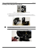


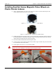
Table Of Contents
- 13-0144 - Exhibit Cover.pdf
- 98-1135 installation manual.pdf
- Chapter 1: Pre-Installation 7
- Chapter 2: American Index Cover & Gas Module Removal 23
- Chapter 3: Rockwell Index Cover & Gas Module Removal 27
- Chapter 4: Schlumberger Index Cover & Gas Module Removal 31
- Chapter 5: Sprague Index Cover & Gas Module Removal 35
- Chapter 6: American Mini Switch Kit Installation 39
- Chapter 7: Rockwell Mini Switch Kit Installation 47
- Chapter 8: Schlumberger Mini Switch Kit Installation 51
- Chapter 9: Sprague Mini Switch Kit Installation 55
- Chapter 10: American GPR Configuration and Waterproofing 61
- Chapter 11: Rockwell GPR Configuration and Waterproofing 67
- Chapter 12: Schlumberger GPR Config & Waterproofing 73
- Chapter 13: Sprague GPR Configuration and Waterproofing 77
- Chapter 14: American GPR-P Index Cover & GPR Install 81
- Chapter 15: Rockwell GPR-P Index Cover & GPR Install 85
- Chapter 16: Schlumberger GPR-P Index Cover & GPR Install 89
- Chapter 17: Sprague GPR-P Index Cover & GPR Install 93
- Appendix A: American Changing GPR Orientation 99
- Appendix B: Rockwell Changing GPR Orientation 103
- Appendix C: Schlumberger Changing GPR Orientation 105
- Appendix D: Sprague Changing GPR Direction 107
- Appendix E: GPR Connection Water Proofing Materials 111
- Table 1-1. Typical Gas Meter Module Installation Tool List
- Table 1-2. American Large Diaphragm Meter Mini Switch Kits
- Table 1-3. American Large Diaphragm Meter Dial Wheels
- Table 1-4. Kit, GPR Installation, American Large Diaphragm, Right Bracket #45-1189
- Table 1-5. Kit, GPR Installation, American Large Diaphragm, Behind Index #45-1190
- Table 1-6. Kit, American Large Diaphragm Left Bracket GPR, #45-1193
- Table 1-7. Hardware Kit, American Large Diaphragm #45-1203
- Table 1-8. GPR With Universal Mounting Bracket and Hardware #45-1185
- Table 1-9. GPR Cover Mounting Kit #45-1042
- Table 1-10. Rockwell Large Diaphragm Meter Solid State Pulser Kit
- Table 1-11. Rockwell Large Diaphragm Meter Solid State Pulser Two-Piece Dial Wheel
- Table 1-12. Complete GPR Installation Kit for Rockwell 750 Large Diaphragm Meter #45-1186
- Table 1-13. Kit, Rockwell Large Diaphragm Index Cover Hardware #45-1169
- Table 1-14. GPR Kit with Universal Mounting Bracket and Hardware #45-1178
- Table 1-15. Schlumberger Large Diaphragm Meter Solid State Pulser Kit
- Table 1-16. Schlumberger Large Diaphragm Meter Solid State Pulser Two-Piece Dial Wheel
- Table 1-17. Schlumberger Large Diaphragm GPR Kit #45-1187
- Table 1-18. Kit, Schlumberger Large Diaphragm Index Cover Hardware # 45-1171
- Table 1-19. GPR Kit with Universal Mounting Bracket and Hardware #45-1178
- Table 1-20. Sprague Large Diaphragm Meter Solid State Pulser Kit
- Table 1-21. GPR-P Dial Wheels
- Table 1-22. Complete GPR Installation Kit for Sprague 675 - 1000 Meters #45-1188
- Table 1-23. Sprague Large Diaphragm Index Cover Hardware Kit #45-1114
- Table 1-24. GPR Kit with Universal Mounting Bracket and Hardware #45-1178

Chapter 9 - Sprague Mini Switch Kit Installation Landis+Gyr
58 98-1357 Rev AA Installation Guide
7. Verify that the pulse wheel rotates freely without rubbing the index surface. Rotate the wheel
several times as shown in the next figure to verify that the wheel does NOT contact adjacent
index pointers.
Figure 9 - 7. Pulse Wheel Must Not Contact Adjacent Pointers As It Rotates
A CAUTION: The installed pulse wheel shall not move from the installed position, and cannot
physically contact the index face or other pointers on the index.
If contact occurs, Landis+Gyr recommends replacing the metal pointer index with an index
using plastic pointers so that the Dual Set-Screw Balanced Pulse Wheel can be used.
If pulse wheel contact with the adjacent proving pointer tip is unavoidable, 1/4 of the
adjacent proving pointer tip may be removed with diagonal cutters, but only with permission
from the utility customer.
8. Install the index onto the meter using the original screws that were placed aside in the first step
of this process. If the index has a brass mounting bracket, tighten the index screws to a torque
value of 6 - 12 inch-pounds. If the index uses a plastic mounting bracket, tighten the index
screws to a torque value of 15 - 20 inch-pounds.
A CAUTION: Use caution when tightening the index screws to prevent damage to the index.
9. Confirm that the index’s center of rotation is aligned with the meter dog’s center of rotation.
Adjust the index alignment as needed. The magnet wheel center of rotation must be aligned
with the meter index drive mechanism center of rotation, shown by RED ARROWS in the
following photos.
Figure 9 - 8. Wheel Center Of Rotation Must Align With Meter Drive Center Of Rotation