
All Purpose Seedeer Operator's Manual


8
Section 1: Assembly & Set-up
APS1548, APS1560, APS1572 & APS1586 All Purpose Seeder 313-354M
5/13/08
Land Pride
Table of Contents
Mud Scraper Installation (Optional)
Optional mud scrapers are available from your local
Land Pride dealer. A scraper bundle consists of one rear
roller scraper and two front roller scrapers and are
identified by the rear roller type and seeder planting
width.
Refer to “Torque Values Chart For Common Bolt Size”
on page 28 when tightening hardware.
Front Mud Scrapers
Refer to Figure 1-4:
Land Pride Mud Scrapers
Part No. Part Description
APS1548
313-431A SPIKE SCRAPER BUNDLE . . . S/N 567003+
313-432A PACKER SCRAPER BUNDLE . S/N 567003+
APS1560
313-458A SPIKE SCRAPER BUNDLE
313-459A PACKER SCRAPER BUNDLE
APS1572
313-429A SPIKE SCRAPER BUNDLE. . . . S/N 547969+
313-430A PACKER SCRAPER BUNDLE . . S/N 547969+
APS1586
313-449A SPIKE SCRAPER BUNDLE
313-453A PACKER SCRAPER BUNDLE
IMPORTANT: Some units will not accept a Mud
Scraper attachment. Please be sure of your serial
number to verify.
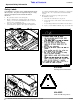
Front Mud Scraper Installation
Figure 1-4
Left Hand Roller
Right hand Roller
25607
Direction
of T
ra
vel
1. Attach spike scrapers (#3) to scraper hangers (#2)
with 3/8"-16 x 1 1/4" GR5 round head square neck
bolts (#5) and hex flange lock nuts (#6). Draw nuts up
snug, do not tighten until after completing
adjustments in Section 3.
2. Attach scraper hangers (#2) to the front rollers with
four 3/8"-16 x 1" GR5 hex head cap screws (#4),
3/8" lock washers (#8) and 3/8" flat washers (#7).
Draw nuts up snug, do not tighten until after
completing adjustments in Section 3.
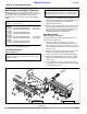
Rear Mud Scraper
Refer to Figure 1-5 on page 9:
The instructions below apply to both the rear packer
roller and rear spike roller.
1. Lower rear roller to ground level to compress
spring (#6). Adjust 3-point lift height to make sure
roller arm (#1) is positioned so that there is space
between the arm and stop blocks located above and
below the arm.
2. Support seeder frame at this height to keep seeder
frame from creeping lower during assembly.
3. Shut tractor engine off and engage parking brake.
4. Attach vice grips tightly to the spring rod and tight
against the spring rod guide bar to retain spring
compression.
5. Loosen bearing set collar screw (#2) and remove
lock nut (#3), cap screws (#4) and lock washers (#5).
Keep hardware for reuse.
NOTE: Do not tighten bolts (#4 & #5) until after
adjustments have been made. See “Mud Scraper
Adjustment (Optional)” on page 14 for instructions.