ADX-2400D AUDIO DISTRIBUTION AND DELAY SYSTEM (AES Digital I/O) Installation and Operation Manual Software Version 1.3 October, 2007 Lance Design / 27 Fairview Avenue / Ridgefield, Connecticut 06877 Tel: 203-894-8206 / Fax: 203-894-8207 www.lancedesign.
WARRANTY STATEMENT This equipment is warranted to be free of defects in materials and workmanship for a period of two years from date of delivery. Any necessary repairs resulting from defects in materials or in manufacture will be made free of charge provided that the equipment has not been subjected to mechanical or electrical abuse, or modification, as determined by Lance Design, and also that the equipment is returned to Lance Design with prior authorization.
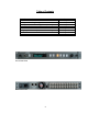
Table of Contents Quick Operation Guide Menu Items Saving and Recalling Configurations Locking Setups and Menus [options dipswitch] General Operation Audio Network Designing the Network [Important Information] Installation Specifications Front Panel View Rear Panel View 3 Page 4 Page 5 Page 8 Page 8 Page 9 Page 10 Page 12 Page 15 Page 16
QUICK OPERATION GUIDE To Select Output Channel (or Channels) to Adjust Press ‘OUTPUT SELECT’ button, and turn knob until desired channel is selected.
To Adjust Level (for current output or group of outputs) The output level can be adjusted in 0.25 dB increments. Maximum gain is +12 dB. To adjust, press the 'LEVEL' button, and turn the knob. To Adjust Delay (for current output or group of outputs) The delay of each output can be independently adjusted from zero delay through 680 milliseconds, which corresponds to more than 20 frames at 30 frames/sec. The delay is adjusted by first pressing the 'DELAY' button, then turning the knob to adjust.
Item 04 – TX 1-8 Bundle (000-999) Packet assignment for network transmitter 1, which corresponds to audio outputs NET 01 – NET 08. Item 05 – TX 9-16 Bundle (000-999) Packet assignment for network transmitter 2, which corresponds to audio outputs NET 09-NET 16. Item 06 – TX 17-24 Bundle (000-999) Packet assignment for network transmitter 3, which corresponds to audio outputs NET 17 – NET 24.
Item 11 - to Recall Config Pressing the 'MENU SET' button will recall the configuration stored in the file selected in menu item 09 above. The following items are STATUS items, and are only to display status information. They may not be changed by the user. Status Item 01 – NET RX 1 Status (Active or Idle) Displays ACTIVE status if data is being received by network receiver 1. This receiver corresponds to net inputs 1-8.
Status Item 05 – NET TX 2 Status (Idle or Number of Receivers) Same as above for net outputs 9-16. Status Item 06 – NET TX 3 Status (Idle or Number of Receivers) Same as above for net outputs 17-24. Status Item 07 – Conductor Status (Another Unit or This Unit) Indicates if the network conductor ('sync generator') is this unit or not. Status Item 08 – PCB Temperature ( degrees Celsius) Indicates temperature of sensors on main PCB. Normal temperature is in the 35-45 degree range.
Saving and Recalling Configurations The menu settings and the source, level, and delay settings are stored automatically after 20 seconds of panel inactivity in a 'default' flash memory. This is the memory which is restored automatically when the unit is first powered up. You may also save configurations in three user memories. First select the desired memory using the menu (Config Item 09), then select ' To Save Config' (Config Item 10), and press the MENU SET button.
General Operational Notes The ADX-2400 is designed to provide delay, level control and distribution for effects or commentary audio. The system can be used for stand-alone delay of 24 AES audio channels (12 pairs), or can be used to transmit and receive audio signals via a standard Ethernet data network (24 transmit and 24 receive channels simultaneously), or the combination of both functions. The system is 'output oriented'.
The Ethernet Part The Ethernet transmission uses the Cirrus Audio 'Cobranet' system, which is an industry standard. It is a professional, highly-reliable system which packs audio data into 'bundles' of 8 channels. The bundles are given numbers from 1 to 999. The first 255 are 'broadcast' bundles which can be received by any number of receivers, so long as the receiver is set to the same bundle number. The rest are 'unicast' bundles, which will only be received by one receiver at a time.
Setting Bundle Numbers The 24 transmit and 24 receive audio channels in the ADX are divided into 8channel groups. These groups are assigned to network channels or 'bundles'. There are six bundles per ADX unit, three for receive and three for transmit. Each of these bundles can be assigned a three-digit number from 000 – 999. (Note that the Cobranet system allows numbers as high as 65000, but they are limited in the ADX2400 to 999).
Exceeding this bandwidth limit will cause dropouts in the audio, and in severe cases may cause other problems such as sync and control problems. An Ethernet switch, which generally forms the hub of a network, can partition the traffic so that bundles only go the receivers which are listening to them. Since each ADX frame only has three receivers, this can eliminate network traffic problems if each bundle is a unicast bundle (one transmitter to one receiver).
Cobranet 'Discovery' PC Application Cirrus Logic, the developers of Cobranet, make available on their website a nice PC application called 'Cobranet Discovery', or 'Disco'. It can be downloaded and installed on any PC running Windows XP. It allows the computer to be attached to the audio network and provides a variety of information about the attached network devices. Documentation is available on their website: www.cobranet.info, or at www.lancedesign.com.
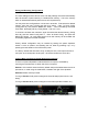
Installation The ADX-2400D is designed to be installed in a standard 19" equipment rack. There is a cooling fan on the rear panel which draws air in through the sides of the cabinet and exhausts hot air through the rear panel. The unit should not be installed in such a way as to block the vents on the side panels, or air flow from the rear panel fan. The unit is designed to operate on 95-250 volts AC, 50 or 60 Hz. The power supply is an wide-range switching supply, so no voltage selection needs to be made.
ADX-2400D Specifications Local Input Channels Local Output Channels AES Reference Input Output Phase Lock Accuracy Input Phase Requirements Sample Rate Converters Output Impedance Input Impedance Digital Processing and Delay Cobranet Transmission Sample Frequency Adjustable Delay Range Minimum Delay (AES in to AES out) Minimum Delay (through Ethernet) Headphone Jack Menu Remote Control VU Meter Display Power Requirements 24 AES on 12 unbalanced (BNC female) connectors, 1v p-p 24 AES on 12 unbalanced (BNC f