Power Products by Lamar Technologies ALPHA C-25 BATTERY CHARGER OPERATING MANUAL Lamar Technologies LLC 14900 40th Ave NE, Marysville WA, 98271 360-651-8869 www.lamartech.
TABLE OF CONTENTS 1. 1.1 1.2 2. 2.1 2.2 2.3 3. 3.1 3.2 3.3 3.4 4. 4.1 4.2 4.3 4.4 4.5 4.6 SYSTEM OVERVIEW ................................................... 3 SYSTEM OVERVIEW ............................................................ 3 DISPLAYS AND CONTROLS ................................................ 3 INSTALLATION ............................................................ 6 LINE VOLTAGE ..................................................................... 6 TERMINALS.........................
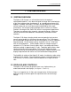
1. SYSTEM OVERVIEW 1. SYSTEM OVERVIEW 1.1 SYSTEM OVERVIEW The Alpha C-25 Charger is a self-contained unit for charging of rechargeable batteries. It has been designed to charge one or two batteries of the same voltage rating simultaneously, to a combined maximum of 25 amperes. At 40 lbs. and 15 by 5 ¾ inches (381 by 146mm) the C-25 takes minimal space and can easily be moved to add flexibility to the work environment.
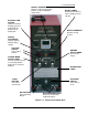
1. SYSTEM OVERVIEW DIGITAL CHARGE TIMER Displays elapsed charge time.
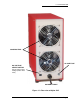
1. SYSTEM OVERVIEW COOLING FANS AC LINE FUSE AC VOLTAGE SELECT SWITCH Selects mains input voltage (120 or 230 volts) AC MAINS CABLE Figure 1–2. Rear view of Alpha C-25 ALPHA C-25 Manual V2.1.
2. INSTALLATION 2. INSTALLATION 2.1 LINE VOLTAGE The Alpha C-25 can operate on either 120 or 230 Volts AC. The desired line voltage can be selected on the rear of the unit. CAUTION: Ensure that the unit is set for the appropriate line voltage before operation. A. On the back of the unit locate the AC voltage select switch. B. Set switch for appropriately marked AC voltage (120 or 230 volts). C. For 230 VAC operation, the 120 VAC plug must be replaced with one for 230 VAC in required configuration.
2. INSTALLATION The rear of the unit has air flow for cooling. Allow at least 6" (150 mm) of separation from the wall and adjacent equipment in order to maintain proper air flow. NOTE: In non air-conditioned rooms it is recommended that circulating or extracting fans be used to aid in the removal of heated air. NOTE: Operation in dusty or otherwise dirty air environments will severely reduce the cooling capacity of the fans and can lead to premature failure. 3.
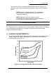
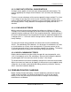
3. OPERATING GUIDE As shown by the curve in figure 3-1 the cell voltage of a discharged battery rises rapidly when the battery is first placed on charge. The extent of the initial rise depends on the charging rate. As the charge continues, the voltage rises at a slower rate and eventually levels off when a full state-of-charge is reached. It can be seen that the specific gravity reading lags behind the rate of ampere-hour return during most of the charging cycle.
3. OPERATING GUIDE 3.2.2 CONSTANT-POTENTIAL CHARGE METHOD A charge source applies a fixed (constant) voltage (potential) to the battery. The current supplied by the charge source fluctuates (rises and falls) with the battery voltage. There are several advantages of the constant-potential charge method. First, there is less danger of gassing at an excessive rate. Secondly, batteries of the same nominal voltage but with different capacities can be connected in parallel directly to the charging source.
3. OPERATING GUIDE It is recommended that a visual inspection of the battery is carried out in conjunction with testing and charging batteries. The charging, unless otherwise specified in the manufacturer's CMM/ ICA, shall be conducted at room ambient temperature of 70°F to 85°F (21°C to 29°C). 3.3.
3. OPERATING GUIDE 3.4 CHARGE TIME 3.4.1 TIMER UNIT SETTING The Alpha C-25 has a built in timer, allowing charge time settings from 0.1 to 999.9 minutes. 3.4.2 CHARGE TIME SETTING The charge time will be set based on the state of charge of the battery and at which rate the battery is being charged. Refer to your battery manufacturer's CMM (Component Maintenance Manual) or ICA (Instructions for Continued Airworthiness) for the most accurate information. C.
3. OPERATING GUIDE E. CONNECT ONE OR TWO BATTERIES Connect the battery DC cable(s) to the Alpha C25 DC Line Connectors on the front of the unit. For single battery always use “BATTERY 1” output. Connect the other end of the cable(s) to the battery (or batteries). Ensure the connectors are plugged in completely. F. SET BATTERY VIEW Set the battery view switch to “VIEW BATT. 1” G. SWITCH ON MAINS POWER Turn on the AC on/off power switch.
3. OPERATING GUIDE H. PUSH START BUTTON The timer starts. The On lamp and the red LED on the timer illuminate. The voltmeter displays the battery terminal voltage and the ammeter reads zero. I. SET CHARGE CURRENT 1. FOR CONSTANT-CURRENT CHARGING Turn the Ampere Adjust knob until the desired charge current has been reached. The charge current is displayed on the ammeter as the current is being adjusted. 2.
3. OPERATING GUIDE J. WAIT FOR THE CHARGE TO AUTOMATICALLY COMPLETE During the charging of the battery the battery voltage, charge current, and elapsed charge time are displayed. For the constant-current method the current remains constant while the voltage increases during the time of charging. For the constant-potential method the charger’s end voltage remains constant while the current starts at a high value and gradually approaches zero as the battery approaches a full charge.
4. CALIBRATION AND MAINTENANCE 4. CALIBRATION AND MAINTENANCE 4.1 OVERVIEW OF CALIBRATION The Alpha C-25 has been calibrated before shipment from the manufacturer. A certificate of calibration with test instruments traceable to the National Institute of Standards and Testing has been issued and is enclosed in the back of this manual. To ensure error-free operation over time, calibration should be verified every 12 months depending on usage and changes in surrounding environment. 4.1.
4. CALIBRATION AND MAINTENANCE 4.4 SHUNT VERIFICATION The Alpha C-25 internal shunt is calibrated and certified by the shunt manufacturer. The shunt is a linear resistive device consisting of a heavy brass base and heavy manganin (copper alloy) resistance. It is not necessary to calibrate the shunt, however the shunt could be verified with the help of an external calibrated shunt and a millivoltmeter (see figure 4-3). EXTERNAL CALIBRATED MILLIVOLTMETER Figure 4-3 Circuit diagram for shunt verification 4.
4. CALIBRATION AND MAINTENANCE 4.6 MAINTENANCE Standard electrical equipment maintenance and cleaning procedures should be followed. 4.6.1 VENTS AND FAN Regularly check that the rear fan vents are clean to ensure adequate cooling of the unit. This is especially important when the unit is placed in a dusty or otherwise dirty air environment. 4.6.2 DC BATTERY CABLES Inspect DC battery cables and connectors periodically. Replace damaged or worn cable. 4.6.
6. SPECIFICATIONS 5. TROUBLESHOOTING Problem A. Unit will not turn on Possible Cause The AC power is not connected to unit AC line fuse is blown. May be due to incorrect AC line voltage setting. B. Unit turns on Timer is set to zero time, but will not start (timing) C. No or very low The lead-acid battery is charge current sulfated and will not support a load High resistance or open circuit in DC cable at quick disconnect, in the cable itself D.
6. SPECIFICATIONS 6. SPECIFICATIONS 120 volts ± 5%, 50/60Hz, 13 amperes or 230 volts ± 5%, 50/60Hz, 6 amperes (selectable on rear of unit) NOTE: Unit will operate ± 10% but with lower max amp ratings at -10%. AC Line Input: Constant Current Mode: Constant Potential Mode Timer Digital Meter Accuracy: Capacity Accuracy Setting Accuracy Setting Units Accuracy Voltmeter Ammeter Cooling: Housing: Outer Dimensions: Height Depth Width AC Line Cord: DC Discharge Cable: Weight: Fuses: Modes: Approx.
APPENDIX A – BATTERY OVERVIEW APPENDIX APPENDIX A - BATTERY OVERVIEW CLASSES OF BATTERIES Batteries can be divided into two major classes: primary and secondary. The primary batteries are not practically reusable once its useful energy has been discharged. The secondary battery is rechargeable. In the following only secondary batteries will be covered. SECONDARY BATTERIES Secondary batteries differ from primary batteries in that they may be recharged.
APPENDIX A – BATTERY OVERVIEW NICKEL-CADMIUM BATTERIES The nickel-cadmium battery is a rechargeable system using alkaline electrolyte (a 31% aqueous solution potassium hydroxide). Nickel-cadmium batteries, which may be vented or sealed, have overcharge capability, high rate charge acceptance and nearly constant discharge voltage. The disadvantages are the high initial and maintenance costs as well as the cost to discard the battery at the end of life.
WARRANTY WARRANTY 1 YEAR WARRANTY POWER PRODUCTS warrants its products to be free from defects in workmanship and material for a one year period from the date of shipment to the distributor, original equipment manufacturer (OEM), or original end user. If any product shall prove to be defective during the warranty period, POWER PRODUCTS will repair or replace such part. There are no warranties which extend beyond the description on the face hereof.
CERTIFICATION OF CALIBRATION REPORT AND CERTIFICATION OF CALIBRATION Lamar Technologies LLC, 14900 40th Ave. NE Marysville, WA 98271 360-651-8869 www.lamartech.com/powerproducts Date of Test ___________ S/N _____________ Model Alpha C-25_ MFR Date ________ Description: Military Battery Charging Battery Discharge Commercial Combination Charger/Discharger NSN: 6130-01-462-6335 & 6130-21-258-4429 Notes on Calibration: 1.
Power Products by Lamar Technologies Designer and manufacturer of aircraft lead-acid and nickel-cadmium battery support equipment since 1980. Headquarters located in Santa Clara, California. CONTACT INFORMATION: Lamar Technologies LLC 14900 40th Ave NE Marysville, WA 98271 360-651-8869 fax 360-651-6677 www.lamartech.com ALPHA C-25 Manual V2.1.