
Manual


Page 2
2-1/2 "
3"
4"
6"
6"
6"
8"
8"
8"
8"
8"
10"
10"
10"
10"
12"
20
20
20
40
40
20
60
60
20
60
20
60
20
60
20
60
9.2
9.2
9.2
18.4
18.4
9.2
18.4
18.4
9.2
18.4
9.2
18.4
9.2
18.4
9.2
18.4
30
30
30
60
60
30
60
60
30
60
30
60
30
60
30
60
93
142
220
191
213
267
281
315
390
393
454
492
526
575
703
754
42
64
100
87
97
121
128
143
177
178
206
223
239
261
319
342
PPS-100-D
PPS-125-E
PPS-150-F
PPS-325-GSA
PPS-520-GGA
PPS-325-G
PPS-600-HSA
PPS-880-HHA
PPS-550-H
PPS-1290-ISA
PPS-825-I
PPS-1460-JSA
PPS-1010-J
PPS-1780-KSA
PPS-1640-K
PPS-2520-KKA
6
7
8
9-3/4
9-3/4
10-3/4
12
12
13-1/4
13-1/4
15-1/4
15-1/4
17-1/4
17-1/4
19-1/4
19-1/4
152
178
203
248
248
273
305
305
337
337
387
387
438
438
489
489
88-3/8
106
120-1/4
124
130
132-1/2
141-1/2
145-3/4
147
150-1/2
154
158
163
170
185
204
2245
2692
3054
3150
3302
3366
3594
3702
3734
3823
3912
4013
4140
4318
4699
5182
5-5/8
5-9/16
6-5/8
8-5/8
8-5/8
8-5/8
10-5/8
10-5/8
10-3/4
10-3/4
12-3/4
12-3/4
14
14
16
16
143
141
168
219
219
219
270
270
273
273
324
324
356
356
406
406
100-175
125-250
150-325
325-520
520-710
325-650
600-910
880-1375
550-1110
1290-1700
825-1450
1460-2040
1010-1800
1780-2420
1640-2560
2520-3180
23-40
29-57
34-74
74-118
118-161
74-148
136-207
200-312
125-252
293-386
187-329
332-463
230-409
404-550
373-582
573-723
Head Loss: Typically, 9-14 feet (2.74-4.27m), except models with optional tail pipes, which will experience a notably greater head
loss. Consult factory for details.
Maximum Particle Size: 1/4 inch (6.3mm)
Maximum Particle Concentration: 1,000 ppm
*Optional tail pipe in place of the flapper valve
Weight
lbs M.N.P.T.
Required
Minimum
Submergence
ft meters
Flow Range
in mm mmU.S. gpm m
3
/
hr
Model
Minimum
Well I.D.
Outside
Diameter
in
mm
in
Length With
Riser &
Flapper Valve
Riser
Size
ft
6.1
6.1
6.1
12.2
12.2
6.1
18.3
18.3
6.1
18.3
6.1
18.3
6.1
18.3
6.1
18.3
meters
Length of
Tail Pipe
kg
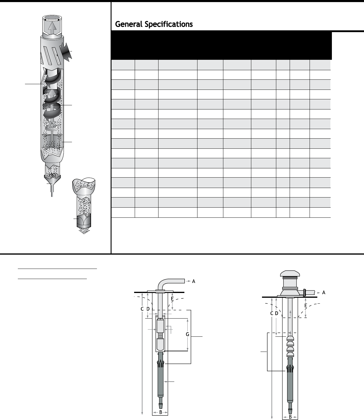
Pump Protection Separators Installation Guide
Flapper Valve Open
Sand discharges
deep into well.
Sand is
centrifugally
separated from
water and tossed
to perimeter
of chamber.
Flapper Valve Closed
Sand accumulates
in separator.
Sandy water is
drawn through
tangential inlet
slots into
separation
chamber.
Sand-free water
is drawn to
center of
separator and up
through vortex
outlet to pump’s
suction.
Sand particles
fall downward,
along perimeter,
to bottom
of separator.
Required Information
Prior to Installation
(Actual Field Conditions)
For Turbine Pumps
For Submersible Pumps
LAKOS
Separator
Pump
Enclosure
Shell
F
H
IMPORTANT:
Separator models with
single-letter designations
(i.e. D, E, F, etc.) require a
minimum submergence of
30 ft (9.2m) below the
drawdown water level.
Models with three-letter
designations require 60 ft
(18.3m) submergence.
Minimum clearance below
separator’s purge discharge:
30 ft (9.2m)
A. Maximum and minimum
ow rate of pump
B. Minimum inside diameter
(I.D.) of well
C. Depth of well
D. Depth of pump setting
E. Pumping water level
F. Maximum diameter of
pump/motor
G. Overall length of pump
and motor
H. Pump’s riser size
Contact LAKOS so Worksheet LS-423 can be completed.