Flow Meters Installation, Operation & Maintenance Manual www.lakemonitors.
This manual is a service guide produced by the manufacturer and provides specific procedures and/or illustrations for disassembly, assembly, inspection, cleaning, and filtration. When followed properly, these procedures will keep your flow meter in top operating condition. It is important for operators and maintenance personnel to be safety conscious when operating or repairing equipment.
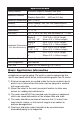
Specifications Casing Material Aluminum, Brass or Stainless Steel #304 Maximum Pressure Aluminum and Brass: Stainless Steel #304: 3500 psi (240 Bar) 6000 psi (413 Bar) Maximum Temperature 240ºF (115ºC) Reading Direct Reading - 360º Ref. Line (Non-Electrical) Scale Accuracy +/- 4% FS, Center 1/3 of scale +/- 2.5% FS Repeatability +/- 1% FS Port Sizes 1/8" - 2" NPTF, #6 - #32 SAE (No Brass) 1/4" - 2" BSP Series 3 1/4", 3/8", 1/2" 1-7/8" O.D. x 6-9/16" Length (48mm O.D. x 167mm Length) 2-3/8" O.D.
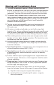
Warning and Precautionary Areas 1) The meters are designed to operate in systems that flow in only one direction: the direction of the arrow on the flow scale. Attempting operation in the reverse direction may cause damage to the meter or other system components. (See page 6 for reverse and bi-directional flow information) 2) The window tube of standard meters is made of Lexan. Lexan can be safely cleaned with soap and water.
INSTALLATION Basic Installation Instructions The meters are mounted in-line and are direct reading. The meters can be mounted in a vertical or horizontal position as long as the fluid is flowing in the direction of the arrow on the flow scale. No straight pipe is required before or after the meter. In fact, 90° elbows can be installed on both ends without any noticeable flow variation. When installing a meter, apply “Thread seal Tape” or “Liquid Thread Sealant” on pipe threads.
Fluid Flow in Reverse Direction The standard meter will not permit flow in the reverse direction (opposite direction to the arrow printed on the flow rate scale). In the reverse direction, the meter will behave in a manner similar to a leaky check valve. Prolonged flow in the reverse direction will cause damage to the standard meter’s internal mechanism that could result in inaccurate readings or premature failure of the meter.
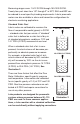
OPERATION Operating Principles Lake has developed a line of unique flow meters which combine the simplicity of a sharp-edged orifice disk and a variable area flow meter. See Illustration 1 “Flow Meter Cross Section” on page 8. The meters are tubular, with all internal wetted parts sealed within the body casing. Running through the center of the body casing is a tapered center shaft which is centered in the bore by pilot disks at each end.
FLOW METER (CROSS SECTION) 3 5 4 Flow n ctio Dire 2 1 13 6 Flow n ctio Dire 7 8 9 10 12 11 Illustration 1 1. End Porting 8. Flowing Sharp-Edged Orifice Disk 2. Body Casing 9. Tapered Center Shaft 3. Magnet Follower 10. Transfer Magnet 4. Window Tube 11. Scale 5. Window Seal 12. Return Spring 6. Seal Assembly 13. Retainer Ring 7.
The indicated flow reading will read high for heavier fluids and low for lighter fluids. A corrective factor can be applied to the standard scale or a special scale can be added at a slight additional costs. When flowing other specific gravities, the basic equations below can be used. For WATER Meters use: 1.0/Specific Gravity x scale reading For OIL Meters use: .873/Specific Gravity x scale reading Viscosity Effect The meters incorporate a unique floating, sharp-edged orifice disk.
Measuring ranges cover 1.5-12 SCFM through 150-1300 SCFM. Twenty-four port sizes from 1/8" through 2" in NPT, SAE and BSP can be ordered to meet specific plumbing requirements. Lake’s pneumatic meters are also available in alarm and transmitter configurations for electronic monitoring applications. Standard Cubic Feet Lake’s meter are calibrated to measure the flow of compressible media (gases) in SCFM – standard cubic feet per minute.
DENSITY CORRECTION FACTORS SCFM (indicated) x (CF) = SCFM (Actual) CF= (F1) x (F2) X (F3) Note: all correction factors need not be used. Table 1. (f1) PRESSURE CORRECTION FACTORS (inlet pressure) psig 25 f1 .56 50 75 100 125 150 175 200 .75 .88 1.0 1.11 1.2 1.29 1.37 f1 = 14.7 + psig 114.7 Table 2. (f2) TEMPERATURE CORRECTION FACTORS ºF f2 10º 30º 50º 70º 90º 110º 130º 150º 1.08 1.04 1.02 1.0 .98 .96 .95 f2 = .93 530 460 + ºF Table 3. (f3) SPECIFIC GRAVITY CORRECTION FACTOR f3 = 1 Sp.
Selecting the Proper Meter To order a pneumatic flow meter the following information is required: n pipe size and port style n media (air, nitrogen, argon,etc.) – for material compatibility and specific gravity considerations n approximate flow range required1 n system pressure: nominal, maximum, minimum n system temperature Flow Range1 Estimating the flow rate in a compressed gas system may seem complicated, but with some research and a few simple equations an educated guess can be made.
TROUBLESHOOTING & MAINTENANCE TROUBLESHOOTING CHART Malfunction: Magnet follower sticks in mid-scale and will not return to the “no flow” position. Possible Cause: Corrective Action: Horizontal/Vertical Mount Particulate, thread seal tape, rust or other foreign matter is holding the internal parts form returning. Disassemble and inspect meter for contamination. Install proper filtration or problem may reoccur.
TROUBLESHOOTING CHART (CONTINUED) Malfunction: Window tube is cracking or crazing. Possible Cause: Corrective Action: Using incompatible cleaning solution on Lexan window tube. Use soap & water or a mild degreaser (Stoddard or Naptha) to clean Lexan tube. To check the compatibility of your cleaning fluid, call General Electric’s Lexan Compatibility Reference line at 800-845-0600. Malfunction: Scale is fogging or coming loose.
Disassembly Important: It is not necessary to remove window tube or window seals to clean the meter. Note also how the meter disassembles for easy of reassembly. Warning: Shut down system before removing meter from flow line. 1. Use a clean dry cloth to remove all foreign material from exterior of meter, especially around threaded ends. Illustration 3 2. Remove meter from the flow line. 3. With the arrow on the scale pointing upward, mount the meter in a vice. See Illustration 3.
IMPORTANT: If inner cartridge does not slide out freely, it may be sign of contamination. The transfer magnet is a powerful ALNICO magnet. Keep it away from metal chips and fillings. They may be hard to remove when reassembling and will cause premature failure. 7. Examine inner cartridge or level of contamination. A. If inner cartridge has a low level of contamination and is functioning properly, no further disassembly is required. Proceed to “Cleaning and Inspection.” See Illustration 5. B.
Cleaning and Inspection Note: If the inner cartridge is damaged or contaminated beyond repair, the complete meter can be sent to the manufacturer for evaluation. The manufacturer will inspect, repair, and/or replace parts as needed according to the warranty. 1. Inspect inner cartridge and body casing for contamination. If the inner cartridge did not slide out freely, it may be a sign of contamination.
CONTAMINATION AND FILTRATION Recommended Filtration The manufacturer recommends system filtration of at least 74 micron filter or a 200 mesh screen. It has been found that if inadequate filtration has caused meter failure, it will normally fail in the open position. Some systems may require a magnetic filter. IMPORTANT: Meter damage caused by excessive contamination is not covered under warranty. Stabilized Contamination The goal of filtration is to create effective protection from system contamination.
Self-Generation Contamination Self-generated contamination is a product of wear, cavitation, fluid breakdown and corrosion. Systems that are carefully flushed, maintained, and have fresh fluid added, mainly have self-generated contamination. In this case, proper filtration can prevent fluid component malfunction.
For downloadable product manuals, data sheets and CAD drawings, visit Lake’s web site today! www.lakemonitors.com LAKE MONITORS 8809 INDUSTRIAL DRIVE, FRANKSVILLE, WI 53126 P: (800) 850-6110 (262) 884-9800 F: (262) 884-9810 WWW.LAKEMONITORS.COM LFMM-1205 Rev. 5/24/2012 © Lake Monitors Inc.