
Users Manual Part 1


31
Nerve Integrity Monitor
1
2
3
4
5
6
7
8
9
10
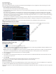
1 Stimulation panel button.
2 Stimulator 1 Name.
3 Stimulator 1 Probe Type.
4 Stimulator 1 Rate and Pulse Width.
5 Stimulator 2. Note: The identical settings for STIM 1 appear for
STIM 2 if it is connected and Stim mode is set to normal.
6 Advanced Settings button.
7 Stimulator 1 Pulse Type.
8 Stimulator 1 Train Count.
9 Stimulator 1 Current Warning Level.
10 Stimulator 2. Note: The identical settings for STIM 1 appear for
STIM 2 if it is connected and Stim mode is set to normal.
Identify STIM 1 and STIM 2 types
1. Press .
The Settings panel appears.
2. Press the Stimulation button.
The Stimulation panel appears.
3. Do one of the following:
• Select STIM 1.
• Select STIM 2.
4. Under the Name eld, press the STIM Name drop down arrow.
A list of pre-dened STIM types appears.
5. Select a STIM type from the list.
6. Click to close the panel.
The system saves the probe name.
The following is an example of a pulse width and rate adjustment performed on the Pulse Width and Rate panels.
Pulse width and Rate diagram (number of pulses per second)
Note: If you selected a Nervassure procedure, then the Stimulator 2 Rate adjustment will be located on the Nervassure Tab.
In the Stimulation advanced settings, the user can change the pulse type which alters the polarity of pulses generated by the
stimulator. Selecting any of the biphasic options enables an Interphase Delay option to appear. Interphase Delay changes the time
between pulses of dierent polarities during a single period. The user can also adjust the train count – number of repetitions of a
pulse for each polarity that occur within a single period. Selecting any train count (the number of pulses in a series of pulses) higher
than one enables an Interpulse Interval. The Interpulse Interval changes the time between pulses that occur in the same polarity.
The following is an example of these adjustments.
FCC use only, not for Medical use