
Users Manual Part 1


18
Nerve Integrity Monitor
Show details/event capture
The Threshold panel displays the threshold settings and enables you to adjust the setting level (in 5, 10, or 100μV increments
depending on the Threshold value). Press to access the threshold settings and then press or to increase or decrease the
value as desired. The system displays the setting in micro-Volts. Press to access the Event Capture toggle button. When event
capture is enabled, the system captures any waveform above the event threshold. The event capture stays on the screen until the
next waveform above the threshold appears.
Volume
The Volume panel displays an adjustable volume setting.
You can adjust sound levels using
or in 5% increments. The default setting is 50.
MONITORING tab Left panel
The NIM Vital left panel contains the following items you can use to adjust the monitoring screen.
Baseline
You can create a baseline and then manually trend future stimulations against the baseline using the trend function. For Nervassure
continuous monitoring, select a Nervassure procedure on the Select Procedure screen during initial setup. For non-Nervassure
procedures, you can use the NerveTrend function (currently available in thyroid procedures) which works similarly to the trend
function.
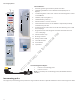
Electrode Check button
The Electrode Check panel checks the integrity of the patient to the patient interface connections.
1
2
3
4
5
1 Electrode check button. Opens/
closes Electrode Check panel.
2 STIM1, STIM2, and Ground status
elds.
3 Electrode Show Details status eld:
• Green check marks. Green
check marks appear when
the electrodes are connected
correctly.
• Spinning icons. Spinning
icons appear while the
system runs the electrode
test.
• Red X. A red X es are
connected incorrectly/fail.
4 The system disables monitoring
when the Electrode Check panel is
open.
5 Show/hide details button.
Note:
• There is no STIM status (blank) if you select Bipolar on the Type Panel
(located in the Advanced Settings/Stimulation Panel).
• There is no STIM2 status (blank) if a single stimulator is connected.
• STIM 1, STIM 2, Ground - If a spinning icon a question mark appears after the system has completed the test, no channel
electrode or ground was connected, so the system reads that as a no value (impedance). You must connect at least one
channel electrode and ground for the system to read STIM 1, STIM 2, and ground impedance.
Electrode check
You can perform an electrode check on the MONITORING screen using
.
FCC use only, not for Medical use