
User Manual


9
CHAPTER 3
Matrix Interface Module
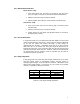
3.1 Interface Module Overview (See Figure 3 – 1 for Photo)
The interface module provides the user the ability to quickly assess the
functions of the Matrix module such as I/O and the mobility to verify
operation of a wireless link in any environment of the user’s choosing.
This chapter describes in detail the functions of the Matrix interface board
that can be verified using the Matrix evaluation software provided in this kit.
Figure 3 -1 Interface Module with 10mW Matrix Module Inserted in Socket
3.1.1 Interface Board Description for Each Location Shown in Figure 3-1
Serial Communications Header (location 1)
• Header that allows the user to monitor the serial TX (MODTXD) and
RX (MODTXD) data lines from section 9 as shown in Figure 3-1
above. The header also provides quick access to Port C pins 0 and
1 on the microprocessor.
Mode Select and Programmer/Debugger Jumpers (location 2)
• Leave jumpers uninstalled for normal operation. Jumpers J2 1-2 and
J8 1-2 should be installed in order to program or debug the CC2430
with the USB Programming/Debugging Port.
10
1
8
9
11
1
2
3
5
4
2
7
6