Operating manual for universal centrifuge Z 306 © Hermle Labortechnik GmbH Z306 Instruction manual.
© Hermle Labortechnik GmbH Z306 Instruction manual.
CONTENT 1. PRODUCT DESCRIPTION ....................................................................................................3 1.1 Usage in accordance with safety standards...................................................................................................... 3 1.2 Brief description.................................................................................................................................................... 3 1.3 Delivery package...............................
CONTENT 2.6 Starting and stopping the centrifuge................................................................................................................ 20 2.6.1 Starting the centrifuge ...................................................................................................................................... 20 2.6.2 The „STOP“ key................................................................................................................................................ 20 2.
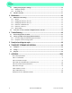
CONTENT 1. PRODUCT DESCRIPTION 1.1 Usage in accordance with safety standards This symbol indicates safety instructions and points to potential dangerous situations. Before using the centrifuge the first time, please read the operating manual. Failure to follow these instructions can result in personal injury an property damage . Intended use includes the observance of all instructions in the instruction manual and carrying out inspection and maintenance.
PRODUCT DESCRIPTION 1.4 Operating and display elements 11 12 1 3 8 4 10 5 6 7 9 2 2 1 central adjuster run parameters 2 0-I power switch 3 LCD control panel display 4 rpm/rcf speed/ g-force 5 accel/decel acceleration- / Deceleration intensity 6 time centrifugation time 7 lid lid release 8 quick short running 9 start start centrifugation 10 stop stop centrifugation 11 prog calling stored programs 12 store program store Z306 Instruction manual.
PRODUCT DESCRIPTION 1.4.1 LCD-Display The following picture shows the individual elements of the LCD-display. Figure 1 Display fields: A-1 Display field – „rpm/rcf“ A-2 Display field – „acc/dec“ A-3 Display field – „time“ Messages/logos of the display fields: M1 „close“ M8 „decel“ M2 „open“ M9 „radius“ M3 „rotor“ M10 „program“ M4 Rotor-No. M11 „error“ M5 „rpm“ M12 „service“ M6 „rcf“ M13 h m s M7 „accel“ 1.5 Signs and indications of the centrifuge 1.5.
PRODUCT DESCRIPTION Reference for loading rotors 1.5.2 Product-nameplate (Example) Company address: Hermle Labortechnik GmbH, Siemensstr. 25, D-78564 Wehingen TYPE: Type designation of the product REF: Order no. of the product SN: Serial number of the product Date of manufacture MAX. Drehzahl: max. allowed speed of the unit KIN. EN.: max. kinetic energy with corresponding rotor U/I/f: Allowable voltage / max.
PRODUCT DESCRIPTION 1.5.3 Warning and information signs Four carrier must be used at all times on four place swing out rotors or damage will occur to the centrifuge. Such damage will not be covered under the product warranty. Attention! Check the fastening of the rotor nut before each run. Take off mains plug before opening the housing or the emergency release 1.5.4 Danger, precautions and warranty This device may only be operated by trained specialist stuff.
PRODUCT DESCRIPTION 1.5.5 Following rules must strictly be adhered to: • Do not operate the centrifuge in case it is not installed correctly. • Do not operate the centrifuge when dismounted (e.g. without housing). • Do not run the centrifuge when mechanical or electrical assembly groups have been tampered with unauthorized persons.
PRODUCT DESCRIPTION 1.6 Installation of the centrifuge 1.6.1 Unpacking the centrifuge Model Z 306 is supplied in a carton. Remove the strap retainer, open the carton and remove the centrifuge. The instruction manual must always be kept with the centrifuge! 1.6.2 Space requirements The centrifuge should be installed on an even solid surface, if possible on a laboratory cabinet / table or some other solid vibration free surface.
PRODUCT DESCRIPTION 1.7 Basic adjustments At commissioning of the centrifuge, you have the options to make the following basic settings: - Acustic signal turn on / off - Keyboard sound turn on -/ off - Volume pre-selection of sound signal - Song selection of sound signal „end of run“ 1.7.1 Access to mode „Operating Data“ If the centrifuge is still turned off, press simultaneously the keys „time“ (6) and „lid“ (7) and turn on the main switch of the centrifuge. Now release both keys again.
PRODUCT DESCRIPTION Figure 3 1.7.2 Sound signal turn on / off Proceed as described under point 1.7.1 to enter this program mode and then press the key „accel/decel“ (5). In the display „accel/decel“ (A-2) flashes the word „service“. Now select the letter „L“. with the adjusting knob (1). As a result appear in the display „rpm/rcf“ (4) the words „On Sound“. If you press the key „rpm/rcf“ (4) now, the word „On“ flashes and you can switch off the sound with the adjusting knob (1) (see figure 4).
PRODUCT DESCRIPTION 1.7.4 Song selection for sound signal - end of run Proceed as described under point 1.7.1 to enter this program mode and then press the key „accel/decel“ (5). In the display „accel/decel“ (A-2) flashes the word „service“. Now select the letter „G“. with the adjusting knob (1). As a result appears in the display „rpm/rcf“ (A-1) the word „ SonGo/Sound“. After pressing the key „rpm/rcf“ (4), you can select a song with the adjusting knob (1). (see figure 6).
PRODUCT DESCRIPTION 1.7.6 Call up operating data (by skilled personnel or service engineer only!) In the mode „Basic Adjustments“ you can call up the operating data of the centrifuge. Please proceed as described under point 1.7.1 to enter this program mode. Press the key „accel/decel“ (5). In the display „accel/decel“ (A-2) flashes the word „service“.
OPERATION 2. OPERATION 2.1 Mounting and loading angle rotor 2.1.1 Installation of rotors Clean the drive shaft as well as the collet with a clean, grease-free piece of cloth. Place the rotor onto the drive shaft. (see figure 9) Take care that the rotor is fully installed onto the motor shaft. Figure 9 Hold the rotor with one hand and secure the rotor to the shaft by turning the fixing nut clockwise.
OPERATION Figure 12: wrong Figure 13: correct (4 tubes) 2.1.3 Loading swing out rotors Loading of the buckets / vessels must be made in accordance to figure 15 It is allowed to operate e.g. a 4-place-rotor with 2 loaded buckets only. But the loaded buckets must be opposite to each other. Make sure that the unloaded buckets also be put inside the rotor (see figure 14 and 15). In principle swing out rotors may not be taken in operation until all buckets or racks are put into the rotor.
OPERATION 2.1.4 Loading and overloading of rotors All approved rotors are listed with their maximum speed and maximum filling weight in „table 2: permissible net weight“ (see APPENDIX P. VI). The maximum load permitted for a rotor, which is determined by the manufacturer, as well as the maximum speed allowed for this rotor (see label on rotor), must not be exceeded. The liquids the rotors are loaded with, should have an max. homogeneous density of 1,2 g/ml or less when the rotor is running at maximum speed.
OPERATION 2.2 Lid 2.2.1 Lid release After the run, respectively closing the lid of the centrifuge, it appears in the display „rpm/rcf“(A-1) the word „close“ (M1). If there is a rotor in the centrifuge, it appears additional the word „rotor“ (M3), as well as the code number of the respective rotor, which is in the centrifuge i. e. „221.28“ (M4). If there is no rotor in the centrifuge it flashes the word „rotor“ (M3) and additional the word „no“ (M4). ).
OPERATION 2.3 Preselection 2.3.1 Preselection of speed / RCF-value Through the key „rpm/rcf“ (4) this pre-selection is activated. By pressing the key once the word „rpm“ (M5) flashes. By pressing the key once again the pre-selection of the centrifugal forces may be chosen. Then it appears the flashing word „rcf“ (M6). You can set the desired values with the adjusting knob (1). In the display (A-1) the regulated value is shown permanently, before, during and after the run.
OPERATION The running time can be pre-selected with the lid open or closed. To activate the setting of the running time press the key „time“ (6). In the display „time“ (A-3) flashes the indication „m : s“ or „h : m“, depending on the previous setting. To set the desired value use the adjusting knob (1). After exceeding of 59 min 50 sec the indication changes automatically into „h : m“. After exceeding of 99 hours 59 min the word „cont” appears in the display „time” (A-3).
OPERATION Figure 19 2.4 Radius correction If you use adapters or reducers it could change the centrifugal radius of the respective rotor. In that case you can correct the radius manually. Please proceed as follows: Press the key „time“ (9) and the key „prog“ (11) at the same time and hold them. In the display „time“ (A-3) appears the word „radius“ (M9). By the adjusting knob (1) you can preselect then the respective radius correction (see table 6, APPENDIX P. X) in steps of 0,1 cm.
OPERATION If a program number is already occupied in the display „rpm/rcf“ (A-1) will appear the words „rotor” (M3) and „22x.xx“ (M4). In case of free program numbers it appears 0. Close the lid of the centrifuge. Now proceed as already described to set all important run parameters. For adaption of data press the key „store“ (12) for approx. 1 second. As a result the word „program“ (M10) disappears.
OPERATION 2.5.3 Leaving program mode To leave the program mode just press the key „prog“ (11). Then inside the display „time“ appears the word „Programm". Set the display to „programm--“ (M10) with the adjusting knob (1). All with number marked passages refer to figure 22. 2.6 Starting and stopping the centrifuge 2.6.1 Starting the centrifuge You can start the centrifuge either with the „start“ key (9) or the „quick“ key (8).
OPERATION 2.7 Imbalance detection In case of the rotor not being equally loaded, the drive will turn off during acceleration. The rotor decelerates to stand still. When in the display “time” (A-3) the word “error” (M11) together with the number “01” appear, the weight difference of the samples is too huge. Weigh out the samples exactly! Load the rotor as described in chapter 2.1.1 and 2.1.2.
MAINTENANCE 3. Maintenance 3.1 Maintenance and cleaning 3.1.1 General Care: Maintenance of the centrifuge is confined to keeping the rotor, the rotor chamber and the rotor accessories clean as well as to regularly lubricating the rotor insert bolts of a swing out rotor (if available). The most suitable lubricant is the offered HERMLE High TEF oil – Order no.: 34-5147. Lubricants containing molycote and graphite are not allowed. Please pay special attention to anodized aluminium parts.
MAINTENANCE 3.1.2 Cleaning and disinfection of the unit 1. Open the lid before you turn off the unit. Disconnect it from the power supply. 2. Open the rotor nut by turning the rotor key counter clockwise. 3. Remove the rotor. 4. For cleaning and desinfection of the unit and the rotor chamber using the above mentioned cleaner. 5. Clean all accessible areas of the device and its accessories, including the power cord with a damp cloth. 6. Wash the rubber seals and rotor chamber thoroughly with water. 7.
MAINTENANCE destroy the plastic. The objects must be thoroughly washed up with distilled water after the cleaning but before the autoclaving. Residues of any cleaning liquids may cause fissures, whitening and stains. Gassterilization Adapters, bottles and rotors may be gassterilized with Ethylenoxyd. According to the duration of the application you may give long enough an airing to the items after the sterilization and before using them again.
MAINTENANCE © Hermle Labortechnik GmbH Z306 Instruction manual.
TROUBLE SHOOTING 4. Trouble Shooting 4.1 Error messages: Cause / Solution The error messages are listed to help localize possible errors faster. The diagnose referred to this chapter may not always be the case, as they are only theoretically occurring errors and solutions. Always, please keep us informed about any kind of error occurring, which is not listed in this chapter. Only through your information we are able to improve and complete this operation manual. Many thanks in advance for your support.
TROUBLE SHOOTING 4.2.2 Description of the error message system The error message „error“ (M11) is shown in the „time“ (A-3) display (see figure 27). Detailed information about possible error messages are in „table 5: error messages" (see Appendix P.IX). Figure 27 © Hermle Labortechnik GmbH Z306 Instruction manual.
TROUBLE SHOOTING 28 Z306 Instruction manual.
REPAIR 5. Receipt of centrifuges to repair Health risk from contaminated equipment, rotors and accessories In case of returning the centrifuge for repairing to the manufacturer, please notice the following: The centrifuge must be decontaminated and cleaned before the shipment for the protection of persons, environment and material. Decontamination certificate at goods return delivery (see APPENDIX P. XIV) We reserve the right to accept contaminated centrifuges.
TRANSPORT / STORAGE / DISPOSAL 6. TRANSPORT, STORAGE AND DISPOSAL 6.1 Transport Before transporting, take out the rotor. Only transport the unit in the original packaging. Use a transport aid for transporting over longer distances to fix the motor shaft. General transportation Air temperature rel. humidity Air pressure ‐25 bis 60 °C 10 bis 75 % 30 bis 106 kPa 6.
TRANSPORT / STORAGE / DISPOSAL 7. APPENDIX EC - Conformity Declaration ............................................................................................... IV Table 1: Technical Data ....................................................................................................... V Table 2: Permissible net weight.......................................................................................... VI Table 3: Max. speed and RCF-values for permissible rotors.............................
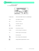
APPENDIX EC - Conformity Declaration EG Konformitätserklärung EC Conformity Declaration Hermle Labortechnik GmbH - Siemensstr. 25 - D-78564 Wehingen – Germany Das bezeichnete Produkt entspricht den einschlägigen grundlegenden Anforderungen der aufgeführten EG-Richtlinien und Normen. Bei einer nicht mit uns abgestimmten Änderung des Produktes oder einer nicht bestimmungsgemäßen Anwendung verliert diese Erklärung ihre Gültigkeit.
APPENDIX Table 1: Technical Data 30 kg Weight without rotor max. speed -1 13500 min 4 x 100 ml 18625 x g max. volume max. RCF allowable density allowable kinetic energy 3 1,2 kg/dm 5595 Nm ( Rotor 221.
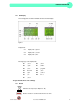
APPENDIX Table 2: Permissible net weight Rotor number 220.50 V08 220.72 V06 220.87 V09 220.87 V10 220.96 V04 220.97 V04 221.12 V03 221.16 V03 221.17 V03 221.19 V02 221.24 V02 221.25 V03 VI Max. speed Permissible 3500 min-1 4000 min-1 13500 min-1 13500 min-1 6000 min-1 6000 min-1 4500 min-1 4500 min-1 12000 min-1 4500 min-1 3250 min-1 5000 min-1 net weight 4 x 200 g 4 x 465 g 24 x 3,4 g 24 x 3,4 g 12 x 25 g 6 x 72 g 4 x 340 g 2 x 400 g 30 x 3,4 g 30 x 32 g 2 x 70 g 6 x 110 g Z306 Instruction manual.
APPENDIX Table 3: Max. speed and RCF-values for permissible rotors Rotor number Max. speed 220.50 V08 220.72 V06 220.87 V09 220.87 V10 220.96 V04 220.97 V04 221.12 V03 221.16 V03 221.17 V03 221.19 V02 221.24 V02 221.
APPENDIX Table 4: Acceleration and deceleration times Rotor number 220.50 V08 220.72 V06 220.87 V09 220.87 V10 220.96 V04 220.97 V04 221.12 V03 221.16 V03 221.17 V03 221.19 V02 221.24 V02 221.
APPENDIX Table 5: Error messages Error-No.
APPENDIX Tabelle 6: Radius correction Rotor no. Swing out rotor 220.72 V04 Adapter/Tube‐ rack Order no. Drawing. no. Radius (cm) Correction (cm) 605.004 220.72.60.03 14,6 0 605.005 605.000/001 705.002 705.003 705.005 705.007 705.008 705.009 705.010 705.012 705.013 705.014 705.015 705.016 220.72.61.03 220.72.06.03 220.72.73.04 220.72.74.04 220.72.76.04 220.72.79.14 220.72.80.14 220.72.84.04 220.72.85.04 220.72.62 220.72.63 220.72.64 220.72.65 220.72.66 220.72.
APPENDIX Table 6 (part 2): Radius correction Rotor no. Swing out rotor 221.12.01.02 Adapter/Tube‐ rack Order no. Drawing no. Radius (cm) Correction (cm) 626.003 221.12.09.03 14,8 0 626.000 626.001 626.002 626.004 626.005 626.006 626.007 626.008 626.009 626.010 626.011 626.012 626.013 626.014 626.015 221.12.08.03 221.12.10.03 221.12.07.03 221.12.11.03 221.12.13.03 221.12.06.03 221.12.12.03 221.12.16 221.12.17 221.12.18 221.12.19 221.12.20 221.12.21 221.12.22 221.12.
APPENDIX Table 7: Abbreviations used Symbol / Abbreviation U (=rpm) [min‐1] RZB(=rcf) [x g] PP PC accel decel XII Unit ‐ ‐ ‐ ‐ Description revolutions per minute relative centrifugal force Polypropylen Polycarbonat acceleration deceleration Z306 Instruction manual.
APPENDIX Redemption form / Decontamination certificate Decontamination certificate at goods return delivery Enclose at all returns of equipment and assemblies absolutely! Surname; last name: _____________________________________ Organization / company: _____________________________________ Street: _____________________________________ ZIP CODE: _____________ place:____________________ Telephone: _____________ fax:____________________ E-Mail: _____________________________________ Pos.
APPENDIX Signature of the authorized person: ________________________________________ XIV Z306 Instruction manual.
NOTES © Hermle Labortechnik GmbH Z306 Instruction manual.
31 Mayfield Ave. Edison, NJ 08837 • USA • US • toll free: 888-LABNET1 • fax: 732 417-1750 • International • phone: +1-732-417-0700 • fax +1-732-417-1750 website: http://www.labnetinternational.com email: labnetinfo@corning.com Technical modification rights reserved. ©HERMLE Labortechnik GmbH 2012 Z306 Instruction manual.