IN STRUC TION MANUA L Laboratory Equipment Pty Ltd email: sales@labec.com.au Ph: 02 9560 2811 • Fax: 02 9560 6131 www.labec.com.
Shaking Water Bath Instruction Manual Model : J-SWB19, J-SWB35, J-SWB60 Please read this Instruction Manual carefully before use.
Contents Use of Instruction Manual ‥‥‥‥‥‥‥‥‥‥‥‥‥‥‥‥‥………..‥‥‥‥‥‥ 3 To SUPERVISOR in charge of this equipment SAFETY SYMBOLS ‥‥‥‥‥‥‥‥.‥‥‥‥‥‥ 4 ‥‥‥‥‥‥‥‥‥‥‥‥‥‥‥‥‥………...‥‥‥‥‥‥‥‥ 5 Safety Precautions ‥‥‥‥‥‥‥‥‥‥‥‥‥‥‥‥‥‥………….‥‥‥‥‥‥‥‥ 6 1. Intended use of the Apparatus ‥‥‥‥‥‥‥‥‥‥‥…….‥‥‥‥‥.‥‥‥‥ 8 2. Feature of product ‥‥‥‥‥‥‥‥‥‥‥‥‥‥‥‥‥‥…………‥‥.‥‥‥‥‥ 8 3. Appearance ‥‥‥‥‥‥‥‥‥‥‥‥‥‥‥‥‥‥‥‥…………...‥‥‥.‥‥‥‥‥ 9 4. Installation ‥‥‥‥‥‥‥‥‥‥‥‥‥‥‥‥‥‥‥‥…………….‥‥‥.‥‥‥‥‥ 10 5. Name and functions of controller ‥‥‥‥‥…….
Use of Instruction Manual ● Please read through and understand this Instruction Manual before operating the product. After reading, always keep the manual nearby so that you may refer to it as needed. When moving the product to another location, be sure to bring the manual as well. ● If you find any incorrectly arranged or missing pages in this manual, they will be replaced. If the manual it gets lost or soiled, a new Instruction Manual can be purchased.
Safety Precautions The following safety precautions must be observed and followed to avoid fire hazard, electrical shock, accidents, and other failures. Keep them in mind and make sure that all the precautions are observed and followed properly. LABORATORY EQUIPMENT PTY LTD assumes no liability nor any responsibility against any damages, accidents, or problems resulting from negligence of the precautions.
Installation ● When installing products be sure to observe Installation Precautions described in this manual. ● To avoid electrical shock, connect the protective ground terminal to electrical ground (safety ground). ● When applying power to the products from a switchboard, be sure work is performed by a qualified and licensed electrician or is conducted under the direction of such a person. ● Be sure to use the AC power cable provided.
1. Intended use of the apparatus. Shaking Incubators are used in biological experiments to allow growth of organisms in optimal conditions of temperature, carbon dioxide and humidity. Shaking Incubator is used for cultivation of bacteria or germs in smaller volumes (10 - 500㎖) at a constant temperature. Shaking water baths are designed for controlling temperature and agitating samples. They are used for warming liquid samples to sustain or impede reactions.
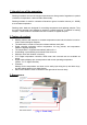
[ Fig.2 : Magnetic water drain ] [ Fig.3 : Main power switch ] 4. Installation. 4.1 Precautions for Installation ● ● ● ● ● ● ● ● ● ● ● ● ● ● ● This equipment is designed and manufactured to operate properly only in use of rated voltage. Refer to specification section of this manual for rated voltage before installation. Use AC power cable that comes with (or installed to) the product. Do not touch the Power Cord wet handed. Avoid locations where the equipment is exposed to direct sunshine.
4.2 How to install ● ● ● ● Use with a minimum distance all around of 20cm from walls of other items. Locate in a flat place. Connect the power cord to an outlet with earthling point. In case of connecting to an outlet without earthling point, connect lead wire to the earth after connecting grounding adapter. 4.3 How to ground Earth wire ● ● Earth wire must be grounded to prevent any electrical accidents. Improper or no grounding may cause electrical shock.
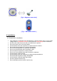
5. Name and functions of controller. 5.1 Name of the controller. [ Fig.4 : P.I.D. temperature controller ] ① : PV display window : Indicating current temperature ② : SV display window : Indicating temperature setup. : Heating Status Display : Lamp is turned on when heater is ON. : Overheat Status Display : Lamp blinks when it is overheated. : TIMER Function Status Display : Lamp is turned ON when timer function is in use.
: Shift Key : Used to move decimal point of setting value. : Increase Value Key : Used to change setting value. : Auto Tuning Status Display : Lamp blinks when automatic tuning is in process. : Auto Tuning Key : AT key function is starts if you press AT key for more than 4 seconds. : POWER ON / OFF Key Displays current speed (R.P.M) of shaker in operation. [ Fig.5 : RPM display meter ] Sets shaking speed (R.P.M.) by turing the knob [ Fig.6 : Shaking speed (R.P.M.
■ AT (Auto tuning key) : Displays present time, then temperature in turn when At key is pressed in Normal Display Mode. AT key function starts if you press AT key for more than 4 seconds in Normal Display Mode. By pressing AT key for more than 4 seconds during Auto Tuning Process ends Auto Tuning Process instantly. Displays present temperature when AT key is pressed once during Auto Tuning Process. 5.2 Configuring controller. 5.2.1 Setting Temperature and Time MODE.
5.2.
● ● DO NOT CHANGE the SET VALUE, which is FACTORY SET DEFAULT VALUE ! Changing the SET VALUE may result in MALFUNCTION !
5.2.3 Controller Factory Configuration Mode.
5.2.4 Output type. Main output : * Output by P.I.D control * On during Heating (Heater LED is ON) ● Start Relay When used as START RELAY (when FACTORY CONFIGURATION MODE => SR_A è NON is selected) 5.2.5 How to set automatic tuning for temperature. ● ● ● When temperature difference occurs during operation, press AT key for 4 seconds, and automatic tuning process will begin, and AT lamp (Auto tuning lamp) will start to blink until automatic tuning process is completed.
5.4 How to set the shaker parameters. ● Set the shaking speed(R.P.M) of shaker by turning "Shaking speed (R.P.M.) control dial knob" and the shaking speed(R.P.M) will be displayed on the "R.P.M. meter". 5.5 How to start operation. 1 2 3 4 5 6 7 8 9 Connect the power plug to the power outlet. Turn ON the Main Power Switch Turn ON the POWER ON / OFF Key located on the temperature controller Put the sample in the bath Set and configure the settings by using temperature controller and shaker controller.
6.3 Cleaning electric parts. ● Clean with dry clothes. 6.4 When the equipment is not used for long time. ● ● ● Remove power plug from power outlet. Clean with soft clothes. Pack the equipment in a appropriate way and store in a safe place for storage. 7. Trouble shooting. ① In case apparatus fails to work at all :● Control unit switched off. :Ensure unit is on. ● Power supply shortage :Refer to specification and check whether sufficient power is being supplied. Check if E.L.B is trued OFF.
8. After-sales Service. 8.1 Warranty Faults which is responsible for manufacture in normal condition can be repaired with free for 1 year from purchase date (only, pressure vessel is zero year), and it is desirous to include the following items when requesting A/S (After sales service). ● Part and condition generated fault. (It is necessary to explain in detail within limit of possibility.) ● Model name ● Serial Number ● Purchase date (year, month, date) 8.
9. Specification. 9.
※ Option : Shaking plate (spring wire rack) and lid. 9.2 Component list No Description 1 RPM display meter 2 SSR 3 Relay 4 Motor Specification 12A 25A Model No. Q'ty Manufacturer MP5W-4N 1 Autonics corporation SDA1-240Z 1 UNION ELECOM CO., LTD HR-723 1 Han Kuk Relay SB125GK-S12 1 SPG CO., LTD. 9:1 5 Pt sensor 6 Heater 7 Temp.