User’s Manual WaterPro® BT System with Remote Dispense Models 90152 Series 90153 Series To receive important product updates, complete your product registration card online at register.labconco.com Labconco Corporation 8811 Prospect Avenue Kansas City, MO 64132-2696 800-821-5525, 816-333-8811 FAX 816-363-0130 E-MAIL labconco@labconco.com HOME PAGE www.labconco.
Copyright Information Copyright (C) 2013 Labconco Corporation or its licensor or manufacturer. All rights reserved. The information contained in this manual and the accompanying product is copyrighted and all rights reserved by Labconco Corporation or its licensor or manufacturer. The copyright holder reserves the right to make periodic design changes without any obligation to notify any person or entity of such change. Warranty Labconco provides a warranty on all parts and factory workmanship.
Directive 2002/96 EC: For European users only The symbol “crossed bin” on a product or its packaging indicates that the product should not be treated like household waste when discarded. Instead the product should be disposed of at a location that handles discarded electric or electronic equipment. Proper disposal of equipment containing electric or electronic components will help to reduce pollution effects to the environment or to human health.
Table of Contents Introduction ............................................................................................................................. 1 Using this Manual .......................................................................................................................................................... 1 Safety Information .........................................................................................................................................................
How to Understand WaterPro® BT System messages ......................................................................................... 34 Maintenance ...........................................................................................................................37 Maintenance Schedule................................................................................................................................................ 37 How to Replace the Filter Pack Cartridge ........................
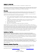
Introduction Using this Manual This User Manual is a guide for use during the installation, normal operation and maintenance of a WaterPro® BT Water Purification System with Remote Dispense. It is highly recommended to completely read this manual and to fully comprehend its contents before attempting normal operation or maintenance of the WaterPro BT System. Safety Information Your WaterPro® BT System should be operated according to the instructions in this manual.
Product Information WaterPro® BT Water Purification System Overview DISPLAY The DISPLAY is used to monitor the water quality and system status. DISPENSING BUTTON KEYPAD The DISPENSING BUTTON is used to get Product Water. The KEYPAD is used to access operating functions and system settings.
Product Information Schematic of Main Components 8 1 2 3 5 6 7 4 10 13 12 9 14 11 1 2 3 4 5 6 7 Booster Pump Inlet Solenoid Valve Filter Pack (Pretreatment and RO Cartridge) RO Reject Solenoid Valve RO Reject Capillary Check Valve RO Permeate Conductivity Cell 8 9 10 11 12 13 14 Tank Distribution Pump UV Lamp 185 nm (UV System) Filter Pack (Ion Exchange Polisher Cartridge) Product Resistivity Cell Remote Point-of-Use (POU) Solenoid Valve Final Filter Operating principle Potable tap water ent
Product Information Technical Specifications Dimensions System Height, Width and Depth • System Shipping Box: Height: 22.5” (57 cm); Width: 16.5” (42 cm); Depth: 25.2” (64 cm) • Remote Shipping Box: Height: 22.5” (57 cm); Width: 16.4” (41.5 cm); Depth: 10.4” (26.5 cm) Weight SYSTEM Operating Weight Dry Weight Shipping Weight WaterPro® BT with remote Dispenser WaterPro® BT (UV) with Remote Dispenser 44.7 lbs (20.3 kg) 22.5 lbs (10.2 kg) 35.1 lbs (15.9 kg) 46.1 lbs (14.3 kg) 23.6 lbs (9.2 kg) 36.
Pre Installation Installation Requirements Feedwater Requirements Type of Feedwater Flowrate Minimum Pressure Maximum Pressure Conductivity Temperature pH Fouling Index Iron Aluminum Manganese Free Chlorine Langelier Saturation Index TOC Potable ≥ 10.7 GPH (40 LPH) ≥ 7.3psi (0.5 bar) ≤ 87.0 psi (6 bar) < 2000 µS/cm 5 to 35 °C 4 - 10 < 10 < 0.1 ppm as CaCO3 < 0.05 ppm as CaCO3 < 0.05 ppm as CaCO3 < 1 ppm < + 0.
Pre Installation Optional Equipment You May Need Wall Mounting Bracket The Wall Mounting Bracket is 9037900. The mounting hardware for attaching the bracket to the wall is not included. Unpacking the WaterPro® BT− What’s Inside? Open the WaterPro® BT System Shipping Box. The carton should contain the Unit, the Remote Stand, the User’s Manual, the Power Cord and an Accessory Bag. Use the checklist included in the Accessories Bag to make sure all other items were shipped and are accounted for.
Installation Preparation of the System A • Open the front cover (this may require removal of the final filter). Locate the tie wrap used to hold the Booster Pump in place during shipping (A). B • Press on the tab of the tie wrap. Remove and pull the tie wrap out. C • Locate the protective foam found at the UV lamp cable. Remove it and discard. Connection of Tubing for a WaterPro® BT System A • Rotate the WaterPro® BT System so you can see the back of the system (see photo A). 1. Feedwater tubing 2.
Installation Feedwater Tubing B • Locate the Feedwater Tubing exiting from the bottom middle of the system (B). A 1/2 inch Female GAZ fitting with a screen filter is attached at the end of this tubing. Unroll and route tubing to Feedwater source. • Apply white tape on the thread of the 1/2 inch Male GAZ valve or fitting of the Feedwater source. C • Connect the GAZ fitting on the end of the feedwater tubing to the Feedwater source.
Installation Pure Permeate Tubing F • Locate the Tank Outlet Valve, the Pure Permeate Outlet Tubing and the adaptor fitting in the Accessories Bag. • Install the Tank Outlet Valve and Pure Permeate Tubing as shown (F, G and H). G H I • Open the Tank Outlet Valve (I). This allows the tank to be emptied of any water in it. This is necessary when the Filter Pack cartridge is flushed with water after it is installed.
Installation Connection of the Ultrapure (Type 1) water dispenser 1 • Locate the Ultrapure (Type 1) water dispenser. The Ultrapure (Type 1) water dispenser and the water system are packaged separately. • The remote Dispenser can be attached to the stand using the two ¼20 x ¾ inch screws which were shipped with the stand.
Installation 2 For system installed under a counter pass the tubing through a hole provided in the counter. • Cut the tie wrap attaching the tubing and cables. • Connect the tubing from the remote dispenser to the water system: black tubing to the black tubing, and transparent tubing to the transparent tubing. 3 • Connect the 2 electrical connectors (Molex + Picoflex) to the PC Board. 4 • Make sure the system operates correctly before installing the cover panel.
Installation Connection of the Power Cord − Turning on the System Power A • Open the front cover of the system (A) – this may require removal of the final filter. This will allow the system to go into STANDBY mode once the system is powered. B • Plug the Power Cord into the system (B). • Plug the other end of the Power Cord into an appropriate source of electrical power (i.e. wall outlet). • Open the Feedwater Supply Valve.
Installation Installation of the Filter Pack cartridge ATTENTION HAZARD Open the Tank Outlet Valve before installing a new Filter Pack cartridge. This keeps the tank from filling until the Filter Pack cartridge is rinsed out. Do not touch the UV Lamp when replacing the Filter Pack cartridge. Installation A • Make sure the front cover is opened (this may require removal of the final filter). B • STANDBY should be viewed on the Display. • Remove the Filter Pack cartridge from its shipping box.
Installation D • Install the Filter Pack cartridge E • Check that the Filter Pack Cartridge it is fully seated into the system ports as shown F • CLOSE THE FRONT COVER. G NOTE: The Tank Outlet Valve should be left open (G).
Installation Flush Mode ATTENTION The Tank Outlet Valve should be left open during FLUSH mode. H • The system will now go into FLUSH mode for 15 minutes (H). This is done to empty the Filter Pack cartridge of air and hydrate the material inside. I • When FLUSH mode is finished, the system will go into FILLING TANK mode automatically (I).
Installation Rinsing the Filter Pack cartridge J • Let FILLING TANK mode run for a minimum of 2 hours with the Tank Outlet Valve open and placed to the drain. This will completely rinse the purification media inside the Filter Pack cartridge. NOTE: For sensitive applications, it is recommended to leave the system in FILLING TANK overnight to ensure complete rinsing of the RO membrane. • Close the Tank Outlet Valve (J) and connect it back to the system if needed. The tank will start to fill up with water.
Installation Installation of the Vent Filter A • Obtain the Vent Filter. • Insert the Vent Filter firmly into the port (A, B). B Installation of the Clear Tubing C • Locate the clear Clear Tubing and the Barbed Fitting from the Accessories Bag. • Screw the Barbed Fitting onto the bottom end of the POU Dispenser (C). D • Push one end of the Clear Tubing onto the end of the Barbed Fitting (D). Place the other end of the Clear Tubing in a sink.
Installation Purging Air from the System A • At this time you should have installed the Filter Pack cartridge, Barbed Fitting and the Clear Tubing. Air trapped in the Filter Pack cartridge should now be purged from the system. • Verify that you have a full tank of RO water by viewing the Tank Level display (A). B • Press the Dispensing Button once to put the system into DISPENSING mode (B). C • Dispense water from the system tank to the 60% level (approximately 3.6 L).
Installation Hydrating the System • At this time, the Final Filter is not installed. Leave the system overnight or for several hours in FILLING TANK mode or PRE OPERATE mode (see Section Operating Modes). The system will regularly recirculate water and rinse off purification media inside the Filter Pack cartridge. Do not leave the system in STANDBY mode. • (The next morning) Press the Dispensing Button once to put the system into DISPENSING mode. • Allow about 1 L of water to be dispensed from the system.
Installation Installation and Rinsing of the Final Filter A • Obtain a Final Filter. • Remove the Clear Tubing and the Barbed Fitting from the POU Dispenser. • Screw the Final Filter onto the end of the POU Dispenser. The Final Filter should be turned until it is hand tight (A). Do not over tighten the Final Filter. ATTENTION B Do not use white tape on the threads of the Final Filter. The POU Dispenser has an O-ring inside which provides a watertight seal. • Press the Dispensing Button once.
Installation How to Calibrate the Flowrate from the WaterPro® BT System (F02) Before calibrating the Product flowrate from the WaterPro® BT System, you will need a 1 L graduated cylinder to measure the total volume of water that will be dispensed. The Final Filter should be installed. 1 Press the Main and “-“ Buttons together to enter the menu. The Display will show F01. 2 Press the Main Button once. The Display will show F02 and the 60 second timer. The graduated cylinder will be blinking.
Installation 4 Measure the total volume of water (in Liters) dispensed from the system using a 1 L graduated cylinder. 5 Press the “+” or “-“ Button to match the volume Display to the volume measured. 6 To exit the menu, press and hold the Main Button for 2 seconds. To display the next menu option, press the Main Button once. The Product Water flowrate is now calibrated.
Installation How to Show Resistivity or Conductivity Units (C01) With Temperature Compensated or non Temperature Compensated values Temperature compensation is a way of ‘standardizing’ Resistivity or Conductivity to measurements that would be seen if the water temperature was 25 °C. 1 Press the Main and “+“ Buttons together to enter the menu. The Display will show C01 and the units chosen. The following Display shows Temperature Compensated Resistivity Units: MΩ.cm @25 °C.
Installation 4 Press the “+” or “-“ Button to select Non Temperature Compensated Conductivity Units: µS/cm. 5 To exit the menu, press and hold the Main Button for 2 seconds. To display the next menu option, press the Main Button once.
Installation How to Set the Resistivity Setpoint (C02) The Resistivity Setpoint is used to inform you when the Product resistivity is low. When the resistivity is below the setpoint, the Resistivity display will flash and the red Pack Alarm will be blinking (see Section How to Understand WaterPro® BT System messages). The factory default resistivity value is set to15 MΩ. cm @25 °C. 1 Press the Main and “+“ Buttons together to enter the menu. The Display will show C01. 2 Press the Main Button once.
Installation 4 To exit the menu, press and hold the Main Button for 2 seconds. To display the next menu option, press the Main Button once.
Using the WaterPro® BT System Understanding the Display The Display is used to view information about the Operating Modes, the Operating Parameters, Maintenance or Alarm messages and the Tank Level. 100 % tank full Operating Modes Operating Parameters Tank Level Maintenance or Alarms 10% UV System only How to Get Water from the WaterPro® BT System Product Water Using the Dispensing Button There are two ways to get water using the Dispensing Button: Press once and release.
Using the WaterPro® BT System RO Water Using the Tank Outlet Valve A • On a WaterPro® BT (UV) system: RO Water is obtained from the Tank Outlet. Open the Tank Outlet Valve when RO Water is needed (A). TANK OUTLET VALVE How to Dispense an Exact Amount of Product Water (F01) 1 Press the Main and “-“ Buttons together to enter the menu. The Display will show F01. 2 Press the “+” or “-“ Button to adjust the exact amount of Product Water (in Liters) needed. Pre-set volumes of water can be adjusted from 0.
Using the WaterPro® BT System 3 Press the Dispensing Button once. The system will dispense water. The Display will show the amount of water dispensed and the Product resistivity. NOTE: To stop dispensing water, press the Dispensing Button once again. 4 To exit the menu, press and hold the Main Button for 2 seconds. To display the next menu option, press the Main Button once.
Using the WaterPro® BT System Operating Modes Standby STANDBY mode is displayed when the front cover is removed. The system will depressurize during which STANDBY will be blinking on the Display for 10 seconds. All system operations are disabled. STANDBY mode is selected before attempting maintenance on the system. Flush FLU (FLUSH) mode is displayed for 15 minutes after a new Filter Pack cartridge has been installed and the front cover has been closed.
Using the WaterPro® BT System Filling Tank FILLING TANK mode is displayed when the tank is being filled with RO water until the 100% Tank Level display. FILLING TANK mode is launched automatically when the Tank Level display is below the 60% level or after a FLUSH cycle has been completed. FILLING TANK mode Water can be dispensed or can be periodically recirculated during FILLING TANK mode if the Tank Level display is above the 10% level.
Using the WaterPro® BT System Dispensing DISPENSING mode is displayed when Product Water is being dispensed. DISPENSING mode occurs because the Dispensing Button was pressed down. The Distribution Pump turns on. The resistivity and temperature of the Product Water is displayed during dispensing. The resistivity and temperature remain displayed for up to 10 seconds after dispensing is stopped. Auto-Dispensing AUTO-DISPENSING mode is displayed when selecting menu option F01.
Using the WaterPro® BT System How to view the Product Resistivity and Temperature in Filling Tank mode or in Pre Operate mode Press: The Display will show the last Product resistivity and temperature values measured during DISPENSING mode or during RECIRCULATION. The values are displayed for 5 seconds. NOTE: The Product resistivity and temperature are displayed automatically during DISPENSING mode or during RECIRCULATION.
Using the WaterPro® BT System How to Understand WaterPro® BT System messages Pack Alarm • The system will prompt you to change the Filter Pack cartridge using a red Pack Alarm icon. The Display will show the red Pack Alarm blinking. The Filter Pack cartridge is changed due to either the amount of time it has been used or from the amount of water that has passed through it. • When the Resistivity display is blinking, the red Pack Alarm will also be blinking.
Using the WaterPro® BT System Flush: Open Tank Outlet Valve • Before FLUSH mode starts, the tank has to be emptied of water. The FLU counter display will be blinking if the system has detected that there is water in the tank. The Tank Outlet Valve must be opened. The system will automatically resume FLUSH mode when the tank is emptied of water.
Maintenance Maintenance Schedule In order to maintain good performance of your water system respect the maintenance schedule and replace consumables as required. What to do When? When the Pack Alarm display is blinking. Filter Pack Replacement How to? See Section How to Replace the Filter Pack Cartridge When the system resistivity display is blinking. After a system or tank sanitization.
Maintenance What to do 38 When? How to? Screen Filter Cleaning 2 times a year or as necessary. See Section How to Clean the Screen Filter Sanitization of the System Once a year. The Filter Pack cartridge will have to be replaced after the sanitization of the system. See Section How to Empty the Tank (C03) and How to Sanitize the System Sanitization of the Tank Once a year.
Maintenance How to Replace the Filter Pack Cartridge ATTENTION HAZARD Open the Tank Outlet Valve before installing a new Filter Pack cartridge. This keeps the tank from filling until the Filter Pack cartridge is rinsed out (A). Do not touch the UV Lamp when replacing the Filter Pack cartridge. Removing the Filter Pack A • Open the front cover to go into STANDBY mode (this may require removal of the final filter). Wait for the system to depressurize.
Maintenance Installation D • Remove the new Filter Pack cartridge from its shipping box. • Remove the protective caps on the ports of the Filter Pack. • Locate the O-rings on the ports. Wet them with water. It is preferable to wet them with ultrapure water. • Install the Filter Pack cartridge until it is fully seated into the system ports as shown (D, E and F). E F • CLOSE THE FRONT COVER. G NOTE: The Tank Outlet Valve should be left open.
Maintenance Flush Mode ATTENTION The Tank Outlet Valve should be left open during FLUSH mode. H • The system will now go into FLUSH mode for 15 minutes (H). This is done to empty the Filter Pack of air and hydrate the material inside. I • When FLUSH mode is finished, the system will go into FILLING TANK mode automatically (I). Rinsing the Filter Pack J • Let FILLING TANK mode run for a minimum of 2 hours with the Tank Outlet Valve open and placed to the drain.
Maintenance Replacing the Vent Filter K • The Vent Filter should be replaced whenever the Filter Pack is replaced. • Remove the Vent Filter (K). • Insert the new Vent Filter into the fitting. See Section Installation of the Vent Filter. Installing the Clear Tubing L • Install the Barbed Fitting and Clear Tubing (L). See Section Installation of the Clear Tubing. Purging Air from the System • See Section Purging Air from the System.
Maintenance Hydrating the System M • Hydrate the system (M). See Section Hydrating the System. Replacing the Final Filter N • See Section How to Replace the Final Filter (N). The System is now ready for use.
Maintenance How to Replace the Final Filter The Final Filter is normally replaced when the Filter Pack is replaced or at an earlier time if it becomes clogged. A clogged Final Filter can reduce the Product Water flowrate. ATTENTION A Make sure the Filter Pack has been hydrated overnight. • Remove the used Final Filter. • Screw the new Final Filter onto the end of the POU Dispenser. The Final Filter should be turned until it is hand tight (A). Do not over tighten the Final Filter.
Maintenance How to Clean the Screen Filter The purpose of the Screen Filter is to prevent large particles or other debris from entering the system. If the Screen Filter becomes blocked with debris, then the Feedwater will not flow freely to the system. It is recommended to clean the Screen Filter twice a year or whenever it may have become clogged. A • Close the Feedwater Supply Valve. • Open the front cover (this may require removal of the Final Filter) to let the system go into STANDBY mode.
Maintenance How to Calibrate the Tank Level (C04) Before calibrating the tank level, the tank needs to be filled to the 100% level or TANK FULL. 1 Press the Main and “+“ Buttons together to enter the menu. The Display will show C01. 2 Press the Main Button 3 times. The Display will show C04. The highest Tank Level display will be blink ing. This means that the highest water level is ready to be calibrated. 3 Press the “+” and “-“ Buttons together to enter the highest water level.
Maintenance 4 Open the Tank Outlet Valve. Allow the tank to be emptied to its lowest water level. NOTE: The lowest water level is not calibrated if the amount of water emptied from the tank is less than 10%. 5 Close the Tank Outlet Valve. 6 Press the “+” and “-“ Buttons together to enter the lowest water level. The Display will exit the menu option and go into FILLING TANK mode. The Tank Level is now calibrated.
Maintenance How to Empty the Tank (C03) The tank can be fully emptied of water through the POU Dispenser. This option is used when performing a system sanitization. Before emptying the tank, it is recommended to remove the Final Filter and to install the Barbed Fitting and Clear Tubing. Place the other end of the Clear Tubing in a sink. 1 Press the Main and “+“ Buttons together to enter the menu. The Display will show C01. 2 Press the Main Button 2 times. The Display will show C03.
Maintenance How to Sanitize the System A system sanitization is performed to eliminate bacteria growth in both the system and in the tank. It is recommended to sanitize the system at least once a year. Things to Know BEFORE you sanitize the System and the Tank HAZARD A All safety precautions must be followed when handling Hydrogen Peroxide. Rubber gloves, safety goggles and a lab coat must be worn to avoid any skin and body contact. • During a system sanitization, the tank will also be sanitized.
Maintenance Sanitizing the System and the Tank C • Open the front cover (this may require removal of the Final Filter) to let the system go into STANDBY mode (C). D • Remove the Vent Filter and install the clear elbow fitting from the Sanitization Kit (D). E • Introduce the male connector of the clear tubing firmly into the elbow fitting (E). F • Inject 200 ml (1 ml = 1 cc) of Hydrogen Peroxide solution (30%) into the 6 Liter tank via the clear tubing (F).
Maintenance G • Close the front cover (G). The system will now go into FILLING TANK mode. H • Let the tank fill up to the 100% level (H). I • Let the system stand for 1 hour for effective bacteria elimination. • (After 1 hour) Remove the Final Filter. Install the Barbed Fitting and Clear Tubing (I). J • Perform an EMPTY TANK (C03) to dispense all the water in the tank (J).
Maintenance K • Once the tank is empty, the system will now go into FILLING TANK mode. Let the tank fill up to the 100% level (K). L • Perform an EMPTY TANK (C03) again to dispense all the water in the tank (L). M • Open the front cover (this may require removal of the Final Filter) to let the system go into STANDBY mode (M). The Filter Pack cartridge, the Vent Filter and the Final Filter will now have to be replaced. Refer to the earlier Maintenance sections for replacement instructions.
Maintenance How to Sanitize the Tank only A tank sanitization is performed to eliminate bacteria growth in the tank only. It is recommended to sanitize the tank at least once a year. Things to Know BEFORE you sanitize the Tank HAZARD A All safety precautions must be followed when handling Hydrogen Peroxide. Rubber gloves, safety goggles and a lab coat must be worn to avoid any skin and body contact. • If you have performed a system sanitization, then you do not need to perform a tank sanitization.
Maintenance Sanitizing the Tank C • Open the front cover (this may require removal of the Final Filter) to go into STANDBY mode (C). D • Remove the Vent Filter and install the clear elbow fitting from the Sanitization Kit (D). E • Introduce the male connector of the clear tubing firmly into the elbow fitting (E). F • Inject 200 ml (1 ml = 1 cc) of Hydrogen Peroxide solution (30%) into the 6 Liter tank via the clear tubing (F). • Rinse the air vent port with 200 ml of purified water.
Maintenance G • Close the front cover (G). The system will now go into FILLING TANK mode. H • Let the Tank Level display go up to the 100% level (H).
Maintenance I • When the tank is full, open the front cover (this may require removal of the Final Filter) to go into STANDBY mode (I). • Let the system stand for 1 hour for effective bacteria elimination. J • (After 1 hour) Check that the Tank Outlet Tubing is secured into the drain. Open the Tank Outlet Valve to drain all the water from the tank (J). K • Close the Tank Outlet Valve (K). L • Close the front cover (L). The system will now go into FILLING TANK mode.
Maintenance How to Replace the UV Lamp (UV System only) The red UV Lamp Alarm will be blinking on the Display when it is time to exchange the UV Lamp. The message is shown when the UV Timer has reached 0 days (see Section How to View or Reset the UV Lamp Timer (C05)). HAZARD No electrical power should be going to the system at this time. Accidental exposure to ultraviolet light can cause damage to the eyes and skin.
Maintenance Removing the UV Lamp ATTENTION D The UV Lamp contains metallic Mercury. Please dispose of the used UV Lamp in a manner that is environmentally safe. • Detach the belt of the UV housing. • Pull the UV housing out so that the UV Lamp cable is accessible (D). NOTE: Use the gloves supplied with the UV replacement kit. E • Unplug the electrical cable from the UV Lamp (E). F • Pull the UV Lamp out of the UV housing by its electrical cable (F).
Maintenance Installing the new UV Lamp G • Ensure that you use the gloves supplied with the UV replacement kit. Carefully insert the UV Lamp into the UV housing (G). H • Plug the electrical cable to the new UV Lamp (H). I • Attach the UV housing with the Velcro® belt (I). J • Install the Filter Pack (J).
Maintenance • Install the Final Filter. ATTENTION If the Filter Pack is not being replaced, then reinstall the old Filter Pack BEFORE powering ON the system. Otherwise, the system will go into FLUSH mode for 15 minutes during which no Product Water will be available. • Close the front cover. • Plug the electrical cord to power ON the system. • Reset the UV Timer. See Section How to View or Reset the UV Lamp Timer (C05).
Maintenance How to View or Reset the UV Lamp Timer (C05) The UV Lamp Timer should be reset only after the UV Lamp has been replaced (see Section How to Replace the UV Lamp (UV System only)). The UV Lamp Timer displays the time left until the UV Lamp needs to be replaced. The Display will show the red UV Lamp Alarm icon blinking when the Timer reaches 0 days. This message is displayed until the UV Lamp is replaced and the UV Lamp Timer is reset.
Maintenance How to Reset the UV Lamp Timer 1 Press the Main and “+“ Buttons together to enter the menu. The Display will show C01. 2 Press the Main Button 4 times. The Display will show C05 and “0” days left on the UV Timer. 3 Press the “+” and “-“ Buttons together. This will reset the UV Timer to 500 (days). The Display will exit the menu. The UV Timer has been reset.
Troubleshooting Problem The Display screen is blank. Possible causes • The power cord is not plugged in. • No source of electrical power. • Main Power Fuse is blown. What to do • Check that the power cord is plugged in. • Check the source of electrical power. • Contact your technical support. In FILLING TANK mode, the Tank Level display is not rising. (The Tank Level display should be rising steadily.) • The Tank Outlet Valve is open. The water in the tank is diverted into the drain.
Troubleshooting Problem Possible causes The last Product resistivity value is not displayed when you press the “-“ button in FILLING TANK mode or in PRE OPERATE mode. • A measurement was not made during DISPENSING mode or during recirculation. What to do • Dispense or recirculate water manually to start a Product resistivity reading again. • The value is out of measurement range. • The Tank Outlet Valve is not open. The system detects that there is water in the tank.
Troubleshooting Problem Possible causes • The UV Timer is exhausted. What to do • Replace the UV Lamp. See Section How to Replace the UV Lamp (UV System only). • After a new UV Lamp has been installed, reset the UV Timer. See Section How to View or Reset the UV Lamp Timer (C05). UV System only • The UV Lamp is not installed correctly or not installed at all. • Power OFF the system and reinstall the UV Lamp. • If the red UV Lamp Alarm is still displayed, then contact your technical support.
Catalogue Numbers for WaterPro® BT Systems for 230 VAC, 120 VAC, 100 VAC: 9015220 WaterPro® BT System with Remote Dispense 115V US Power Cord 9015320 WaterPro® BT System with UV and Remote Dispense 115V US Power Cord 9015230 WaterPro® BT System with Remote Dispense 230V EU Power Cord 9015330 WaterPro® BT System with UV and Remote Dispense 230V EU Power Cord 9015240 WaterPro® BT System with Remote Dispense 230V US Power Cord 9015340 WaterPro® BT System with UV and Remote Dispense 230V US Power Cord 9015260 W
Quick access to most common procedures Checking water quality ............................................................................................................................................... 33 Delivering a fixed ultrapure water volume ............................................................................................................ 28 Delivering ultrapure water ..........................................................................................................................