User’s Manual RapidVap® Vacuum, N2 & N2/48 Evaporation Systems Models 7900000 7900002 7900010 7900012 7910000 7910010 7910012 7910014 7900001 7900003 7900011 7900013 7910001 7910011 7910013 7910015 To receive important product updates, complete your product registration card online at register.labconco.com Labconco Corporation 8811 Prospect Avenue Kansas City, MO 64132-2696 800-821-5525, 816-333-8811 FAX 816-363-0130 E-MAIL labconco@labconco.com HOME PAGE www.labconco.
Copyright © 1999, 2007, 2013 Labconco Corporation. All rights reserved. The information contained in this manual and the accompanying products are copyrighted and all rights reserved by Labconco Corporation. Labconco Corporation reserves the right to make periodic design changes without obligation to notify any person or entity of such change. Warranty Labconco provides a warranty on all parts and factory workmanship.
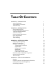
TABLE OF CONTENTS CHAPTER 1: INTRODUCTION About This Manual Typographical Conventions Your Next Step 1 2 3 4 CHAPTER 2: PREREQUISITES Electrical Requirements Location and Exhaust Requirements Vacuum Pump Requirements Vacuum Line Traps Nitrogen Supply Requirements Space Requirements Tools Required Your Next Step 5 6 6 7 8 8 9 9 9 CHAPTER 3: GETTING STARTED Unpacking Your RapidVap RapidVap Components Setting Up Your RapidVap Vacuum Pump Connection Sample Block Nitrogen Gas Connection Exhaust Port Electric
Time Setting Guidelines RapidVap Controls Operating the RapidVap Controls Operating The RapidVap Operational Notes Interrupting a Cycle After it Has Begun End Alarms RS-232 Communications RS-232 Programming Syntax RS-232 Hardware Required 33 35 37 39 40 40 41 41 42 44 CHAPTER 5: MAINTAINING YOUR RAPIDVAP 45 CHAPTER 6: MODIFYING YOUR RAPIDVAP Changing the Sample Blocks Installing the Optional Lid Heater 47 47 48 CHAPTER 7: TROUBLESHOOTING 49 APPENDIX A: RAPIDVAP AND RAPIDVAP N2 COMPONENTS 53 APPEND
CHAPTER 1 INTRODUCTION Congratulations on your purchase of a Labconco RapidVap. Labconco manufactures two types of RapidVaps - one utilizes vacuum and the other utilizes nitrogen as an aid to evaporation. Each model is available for operation on 115V or 230V. Superior evaporation rates are achieved by the unique blending of several gentle forces on the sample.
Chapter 1: Introduction The gyrating motion imparted to the sample causes other, more subtle effects to occur. Excellent mixing of the components in the liquid sample is obtained. Also, as the liquid forms the vortex shape, a centrifugal force is established which forces the liquid outward against the tube walls. This helps prevent bumping and in turn allows the evaporation rate to be optimized.
Chapter 1: Introduction Chapter 6: Modifying Your RapidVap describes how to install other blocks and the optional lid heater. Chapter 7: Troubleshooting contains a table of problems you may encounter while using your RapidVap, including the probable causes of the problems, and suggested corrective actions. Appendix A: RapidVap and RapidVap N2 Components contains labeled diagrams of the components of the RapidVaps.
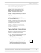
Chapter 1: Introduction ) V N • • Important information is presented in capitalized type in paragraphs that are preceded by the pointer icon. It is imperative that the information contained in these paragraphs be thoroughly read and understood by the user. Information that is specific to a particular model of RapidVap is preceded by a letter icon. The V icon indicates the text is specific to the Vacuum model. The N icon indicates the text is specific to the RapidVap N2 model.
CHAPTER 2 PREREQUISITES Before you install your RapidVap, you need to prepare your site for installation. Carefully examine the location where you intend to install your RapidVap. You must be certain that the area is level and of solid construction. In addition, an exhaust means must be provided and a source of nitrogen must be available for the RapidVap N2. An electrical source must be located near the installation site. Carefully read this chapter to learn: • • • • the electrical supply requirements.
Chapter 2: Prerequisites Electrical Requirements V N If your RapidVap is a Vacuum model, a dedicated electrical outlet is required. This outlet requires a 20 Amp circuit breaker or fuse for models rated at 115V (60 Hz). A 10 Amp circuit breaker or fuse is required for models rated at 230V (50/60 Hz). 115V models are equipped with a 20 Amp NEMA 5-20P plug. 230V models are equipped with a 16 Amp CEE 7/7 plug.
Chapter 2: Prerequisites Vacuum Pump Requirements A vacuum pump must be provided by the user. For most applications, it is recommended that the vacuum pump is capable of a free air flow of 88 L/min and 29.0 inch Hg (31 mbar) vacuum although, in some applications other pumps may be satisfactory or be required. The inlet fitting on the vacuum pump must be suitable for 0.50 I.D. hose. V Biological samples, for example, are often dissolved in water, a high boiling point solvent, and are often heat liable.
Chapter 2: Prerequisites ! CAUTION: When selecting the vacuum pump it is very important to consider the flammability of the solvents that will be used. If the solvents are flammable, an explosion proof vacuum pump is recommended. Vacuum Line Traps When using a mechanical pump which is not corrosion resistant, a trap must be used in the vacuum line to prevent damage from solvent vapors. This is most often a condenser-type trap chilled with dry ice/acetone.
Chapter 2: Prerequisites Space Requirements Refer to Appendix C: RapidVap Specifications for dimensional drawings of the RapidVap. Tools Required Common hand tools are required to set up the RapidVap. A screwdriver or 5/16" socket is needed to attach hose clamps. A tubing cutter or knife is needed to shorten exhaust hoses. If the sample block must be installed or exchanged, attaching nuts on the RapidVap Vacuum and RapidVap N2 require a 7/16" socket.
Chapter 2: Prerequisites 10 Product Service Domestic 1-800-522-7658, International 816-333-8811
CHAPTER 3 GETTING STARTED Now that the site for your RapidVap is properly prepared, you are ready to unpack, inspect, install, and test your RapidVap. Read this chapter to learn how to: • • • • • • • unpack and move your RapidVap. set up your RapidVap. connect the vacuum pump or nitrogen source to your RapidVap. connect the electrical supply source to your RapidVap. properly exhaust your RapidVap. calibrate the vacuum sensor. solvent safety precautions.
Chapter 3: Getting Started Unpacking Your RapidVap The United States Interstate Commerce Commission rules require that claims be filed with the delivery carrier within fifteen (15) days of delivery. Carefully unpack your RapidVap and inspect it for damage that may have occurred in transit. If your RapidVap is damaged, notify the delivery carrier immediately and retain the entire shipment intact for inspection by the carrier. ) DO NOT RETURN GOODS WITHOUT THE PRIOR AUTHORIZATION OF LABCONCO.
Chapter 3: Getting Started Catalog # RapidVap Description 79000-00 79000-01 79000-02 79000-03 79000-10 79000-11 79000-12 79000-13 RapidVap Vacuum System – 115V RapidVap Vacuum System – 230V RapidVap Vacuum System – 115V with lid heater RapidVap Vacuum System – 230V with lid heater RapidVap Vacuum System – 115V with RS 232 Interface RapidVap Vacuum System – 230V with RS 232 Interface RapidVap Vacuum System – 115V with lid heater with RS 232 Interface RapidVap Vacuum System – 230V with lid heater with RS 2
Chapter 3: Getting Started Catalog # RapidVap Description 79100-12 79100-13 79100-14 79100-15 RapidVap N2/48 Evaporation System – 115V RapidVap N2/48 Evaporation System – 230V RapidVap N2/48 Evaporation System – 115V with RS 232 Interface RapidVap N2/48 Evaporation System – 230V with RS 232 Interface Plus the Following: Part # Component Description 79131-01 19660-00 13364-00 13365-00 12556-00 74901-00 74488-00 19116-00 74848-00 Exhaust Hose One (1) Clamp Power Cord – 115V or Power Cord – 230V Heat Tra
Chapter 3: Getting Started pump should be directed to a laboratory fume hood or other laboratory ventilation device. Vacuum pump power connection Optional vacuum pump exhaust hose to ventilation device Vacuum pump inlet fitting Vacuum hose Clamp all connections Hose Optional liquid trap or chilled trap or secondary trap Sample Block If the RapidVap was not shipped with the sample block installed then it must be installed by the user. The sample block must be securely attached to its mounting plate.
Chapter 3: Getting Started ! Never lift the lid if the block is moving. Samples may splash out. Never operate the RapidVap without the sample block securely fastened in place. Excessive vibration will occur. Never attempt to reach into the chamber if the block is moving. Nut or guide rods – 3 required Washer – 3 required Block Mounting stud Temperature sensor Apply heat transfer grease Nitrogen Gas Connection N Turn the gas supply off. Install a barb fitting suitable for a 1/4" I.D.
Chapter 3: Getting Started Exhaust Port If the RapidVap N2 is not located in a fume hood, attach one end of the two inch diameter venting hose that is supplied with the RapidVap to the exhaust port on the right side of the unit. Clamp securely. Route the other end to a fume hood or other laboratory ventilation device. N Electrical Connection Plug the power cord into the receptacle on the back of the RapidVap and plug the other end into a suitable wall power receptacle.
C D D C C D D D D D D D D D D D D D D D C D C D D D C D D C D D D D D D Bases Solvents Acetone Acetonitrile Chloroform Dimethyl Formamide Dimethyl Sulfoxide (DMSO) Ethanol Ethyl Acetate Hexanes Isoproponal Methylene Chloride Toluene COMPONENT MATERIAL Manifold N2/48 Acetal Exhaust Elbow N2 Polyamid (Nylon) Blower Fan N2 Polyamid (Nylon) Exhaust Hose N2 Polyethylene Vacuum Fittings Polypropylene Blower Housing N2 Polypropylene Vacuum Hose PVC Trim Ring Bromyl Butyl O- Rings Neoprene Block Hardware St
Chapter 3: Getting Started • • After each run, clean up all residues, spills, and materials that might have splashed in the chamber using agents suitable for the substance involved. When using a rotary vane pump the oil in the pump should be checked often. It must be changed if it is cloudy, shows particles or is discolored. The useful life of vacuum pump oil can be extended if the vacuum pump is operated for an extended period of time after the RapidVap run is over.
Chapter 3: Getting Started ! Solvents used in the RapidVap may be flammable or hazardous. Use extreme caution and keep sources of ignition away from the solvents. When using flammable or hazardous solvents, both the RapidVap and the vacuum pump should be operated inside a fume hood. If a sample is spilled in the chamber it must immediately be cleaned up.
Chapter 3: Getting Started Your Next Step The installation and setup of your RapidVap is now complete. To learn how to load and operate your RapidVap, proceed to Chapter 4: Using Your RapidVap. To make a modification to the configuration of your RapidVap, proceed to Chapter 6: Modifying your RapidVap. To perform additional diagnostics on your RapidVap, proceed to Chapter 7:Troubleshooting. To learn about the maintenance requirements for your RapidVap, proceed to Chapter 5: Maintaining Your RapidVap.
Chapter 3: Getting Started 22 Product Service Domestic 1-800-522-7658, International 816-333-8811
CHAPTER 4 USING YOUR RAPIDVAP After your RapidVap has been installed as detailed in Chapter 3: Getting Started, you are ready to begin using your RapidVap. Read this chapter to learn how to: • • • • • set operating parameters. operate the controls. properly select and position glassware inside your RapidVap. understand the display. interrupt a cycle after it has begun. ! Do not use the RapidVap in a manner not specified by the manufacturer (refer to Appendix C: RapidVap Specifications).
Chapter 4: Using Your RapidVap Planning V Thoroughly understand procedures and the equipment operation prior to beginning work. The unique performance of the RapidVap Vacuum is dependent upon the proper balance of heat, vacuum and vortexing action. If the proper balance is not established, it is possible to damage or lose a portion of the sample.
Chapter 4: Using Your RapidVap Glassware Selection and Speed Setting Guidelines The speed at which the sample block should oscillate is dependent on the sample tube size and the sample volume. Generally, the tube should be no more than half full. The faster the speed, the higher the sample will vortex giving a maximum surface area and therefore a maximum evaporation rate. However, if the speed is too fast, samples will raise above the top of the tube and be lost.
Chapter 4: Using Your RapidVap TUBE SIZE V N 170 ml SAMPLE VOLUME VORTEX SPEED 50 ml 75 ml 100 ml 125 ml 50% 47% 42% 35% Two sample blocks are available for the RapidVap N2. Recommended speeds are as follows: TUBE SIZE 600 ml 170 ml SAMPLE VOLUME 50 ml 100 ml 200 ml 300 ml 400 ml 450 ml 50 ml 75 ml 100 ml 125 ml VORTEX SPEED 90% 90% 76% 58% 40% 36% 100% 95% 85% 70% Four sample blocks are available for the RapidVap N2/48.
Chapter 4: Using Your RapidVap distributing the weight of the samples and glassware evenly in the sample block. ) IN ORDER TO MAXIMIZE THE PERFORMANCE OF THE RAPIDVAP IT IS IMPORTANT THAT SOME OF THE SAMPLES ARE CLUSTERED AROUND THE FRONT LEFT HAND BLOCK MOUNTING STUD. THE BLOCK TEMPERATURE SENSOR IS LOCATED ADJACENT TO THIS BLOCK MOUNTING STUD.
Chapter 4: Using Your RapidVap Heat Setting Guidelines The evaporation rate achieved by the RapidVap is dependent upon a variety of factors. These include the nature of the solvent, the temperature, the pressure in the vacuum system or the flow of the nitrogen gas in the RapidVap N2, the volume of sample, shape of tubes and vortex speed. Because of the multiplicity of factors it is impossible to give “typical” performance data.
Chapter 4: Using Your RapidVap For example, methanol (which boils at 65°C at atmospheric pressure) boils at 5°C at pressure of 53 mBar. Under these vacuum conditions, the block temperature should be set between 25 to 45°C. The nomogram and equation to follow will help in this determination. Calculating the boiling point: The operating pressure corresponding to the desired boiling point temperature may be calculated for any solvent using the following formula: log P = 2.
Chapter 4: Using Your RapidVap 4. Find “Constant b” for the solvent on the top of the grid. Follow that line until it intersects with the line as drawn between the two points. This point represents the boiling point at the given pressure and the temperature is read off the left or right side of the grid (0-250°C). To determine the operating pressure necessary to achieve a given boiling point: 1. Find the boiling point at normal atmospheric pressure (1 Bar) on the left side of the graph. 2.
Chapter 4: Using Your RapidVap Physical constants: SOLVENT Acetone Acetonitrile Acetylene tetrachloride Benzene Butyl alcohol Carbon tetrachloride Chlorobenzene Chloroform 1.
Chapter 4: Using Your RapidVap Determination of Operating Conditions Applied Vacuum/Boiling Point: ts = Boiling point at 1 bar (normal pressure) tp = Boiling point at P mbar (operating pressure) p = Operating pressure in mbar Example methyl alcohol: 1. Boiling point at normal (1 bar) atmospheric pressure = 65°C. 2. Constant b = 0.160 3. Operating pressure = 130 mBar 4.
Chapter 4: Using Your RapidVap Constant b 0.200 0.195 0.190 0.185 0.180 0.165 0.160 Groups Aliphatic hydrocarbons Aliphatic halogenated hydrocarbons Aromatic hydrocarbons Aromatic halogenated hydrocarbons Ketones Ethers Nitriles Heterocyclic compounds Aldehydes Esters Amines Phenols Acids Alcohols Time Setting Guidelines It is often desirable to stop the concentration process before the solvent is entirely evaporated.
Chapter 4: Using Your RapidVap Cool-Zone When it is necessary to end the concentration process with the sample still dissolved in a small amount of solvent, the time function should be activated and the process time set to allow the solvent sufficient time to evaporate completely out of the large upper portion of the sample tube and into the small lower portion “Cool Zone.
Chapter 4: Using Your RapidVap The tables in Appendix C: RapidVap Specifications indicate approximate times required to evaporate various common solvents. Actual times must be determined by the user. The RapidVap can be set to alarm after a preset period of operation. When the time expires, the RapidVap will give an audible alarm and turn off all functions. V RapidVap Controls The control panel for the RapidVap vacuum model and the RapidVap N2 are shown below with a description about their function.
Chapter 4: Using Your RapidVap RapidVap N2 Model 1 2 3 6 5 4 1. Display – The liquid crystal display (LCD) shows set point parameters and actual measured conditions. 2. Set Point Select Button – To select a parameter to change, press the set point select button directly below the parameter. 3. Run/Stop Button – Used to start or stop a run. 4. Decrease Button – When pressed, the last selected set point will decrease. 5. Increase Button – When pressed, the last selected set point will increase. 6.
Chapter 4: Using Your RapidVap Operating The RapidVap Controls Preheat: To preheat the chamber, press the preheat button. The LED next to the button will illuminate and the display will show: SP: XXC ACT: XXC Press increase or decrease buttons until the desired set point is displayed. The actual block temperature will be displayed to the right. When power is being supplied to the heaters, a bar under the actual temperature will illuminate.
Chapter 4: Using Your RapidVap It is suggested that the user set the vortex speed at a low percentage and gradually increase it after the run is started. This will minimize the possibility of samples sloshing out of the tubes. Reruns of the same protocol may start at the speed determined by previous runs. Change heat set point: To change the heat set point, press the set point select button under the word “HEAT.
Chapter 4: Using Your RapidVap try to maintain can be no deeper than the vacuum level that the vacuum pump can maintain. Select the number of samples that will be run (RapidVap N2 only): Press the set point select button under the word “SAMPLE.” An arrow will point to the last entered set point. By pressing the increase or decrease button, the number of samples or clusters may be changed from 2 to 4 to 6 to 8.
Chapter 4: Using Your RapidVap 11. If the time set point is used, at the end of the set time an alarm will sound. All operating functions will cease. 12. Press STOP to terminate operation if the RapidVap has not already stopped itself. 13. When the evaporation is complete, allow the chamber to stop moving, unlatch the latches, on the RapidVap N2/48 models rotate the cross bar clockwise approximately 1/8", lift the lid and remove the samples. 14.
Chapter 4: Using Your RapidVap secure the latches and press RUN. The RapidVap will resume operation at the same set point parameters and the timer will continue to count down from the time at which the RapidVap was stopped. End Alarms The RapidVap has two means to signal the completion of a run. The first method is determined by the operator when the run time is set as described in the previous paragraph, Time Setting Guidelines.
Chapter 4: Using Your RapidVap RS-232 Programming Syntax The RapidVap only responds to commands sent by the connected computer or terminal – it does not send out commands on its own. The programming syntax has two forms: 1. # [command abbreviation letter] [value]; when the command requires a numeric value. 2. # [command abbreviation letter ]; when the command does not require a numeric value. When the programming syntax contains a numeric value, it will change the operation of the RapidVap.
Chapter 4: Using Your RapidVap #H[xxx]; #L[x]; #N[x] #M[x]; #E; #e; Selects the PRE-HEAT SET POINT of program 9 from 30 to 100 C, will get a xxx;yyy’\n’ response for confirmation.
Chapter 4: Using Your RapidVap RS-232 Hardware Required The connecting cable, Labconco #7484800 is supplied with the unit and is wired as shown below.
CHAPTER 5 MAINTAINING YOUR RAPIDVAP Under normal operation, the RapidVap requires little maintenance. The following maintenance schedule is recommended: As needed: 1. Clean up all spills; remove liquids from chamber. 2. Clean lid and gasket using soft cloth, sponge or chamois and a mild, non-abrasive soap or detergent. Weekly: 1. If the vacuum pump contains oil, check the condition and level. If the oil level is low, add oil.
Chapter 5: Maintaining Your RapidVap Monthly: 1. The rubber components on the RapidVap may eventually deteriorate and require replacement. The effective life of rubber parts depends upon both their usage and the surrounding environment. Check all rubber hoses and gaskets and replace any that show signs of hardening, permanent set or deterioration. 2. Using a soft cloth, sponge or chamois and a mild, non-abrasive soap or detergent, clean the glass lid. 3.
CHAPTER 6 MODIFYING YOUR RAPIDVAP The configuration of your RapidVap may need to be changed to accommodate your needs. For example, you may want to change the sample size you are running so you will need to change the block or you may want to add a lid heater to eliminate condensation inside the lid. Read this chapter to learn how to: • • change blocks. install a lid with heater.
Chapter 6: Modifying Your RapidVap mounting holes. Apply a small amount of heat transfer grease supplied with the RapidVap to the end of the temperature sensor probe that extends up from the bottom of the chamber. Position the block over the three studs in the chamber. Install the flat washers and nuts or manifold guide rods. Tighten securely. Installing the Optional Lid Heater V 48 If a Lid Heater is to be added by the user, first disconnect the main power cord to the RapidVap.
CHAPTER 7 TROUBLESHOOTING Refer to the following if your RapidVap fails to operate properly. If the suggested corrective actions do not solve your problem, contact Labconco for additional assistance. The following failure codes may appear on the display when problems are sensed by the internal self check routine. DISPLAY ERROR CODE CAUSE CORRECTIVE ACTION Top Temp Sensor Top sensor failure Replace top sensor assembly. Connection failure Repair connection.
Chapter 7: Troubleshooting DISPLAY ERROR CODE CAUSE CORRECTIVE ACTION Mem Fail – Push Prog Memory failure Push program button. New memory IC chip Push program button. Bad memory IC chip Call Labconco – Replace IC chip or control PCB. Stalled condition Turn power off. Try to restart after one minute. Call Labconco if error message remains. Excessive speed detected, i.e. >120% Turn power off. Try to restart after one minute. Call Labconco if error message remains.
Chapter 7: Troubleshooting PROBLEM CAUSE CORRECTIVE ACTION Sample in bottom of chamber Gas pressure too high (RapidVap N2) Reduce pressure. Vortex speed too high Reduce speed. Condensation forming inside lid (RapidVap Vacuum) Install lid heater. See page 36. Sample going to dryness (RapidVap N2) Program RapidVap N2 to prevent dryness. Sample sloshing out of tube Decrease vortex speed. Heat setting is too high Decrease heat. Gas supply depleted (RapidVap N2) Replenish gas.
Chapter 7: Troubleshooting PROBLEM CAUSE CORRECTIVE ACTION No gas flow (RapidVap N2) Gas depleted Install new supply of gas. Sample position not activated Activate position per page 30. Nozzle clogged Unplug nozzle with fine wire.
APPENDIX A RAPIDVAP VACUUM AND RAPIDVAP N2 COMPONENTS The following pages list components that are available for your RapidVap. The parts shown are the most common replacement parts. If other parts are required, contact Product Service.
Appendix A: RapidVap Vacuum and RapidVap N2 Components RapidVap Vacuum and RapidVap N2 Components Item Quantity Part No.
Appendix A: RapidVap Vacuum and RapidVap N2 Components 4 5 6 9 8 3 7 11 2 1 10 Product Service Domestic 1-800-522-7658, International 816-333-8811 55
Appendix A: RapidVap Vacuum and RapidVap N2 Components RapidVap Vacuum Components Item Quantity Part No.
Appendix A: RapidVap Vacuum and RapidVap N2 Components 33 27 26 25 34 24 31 28 29 30 23 21 35 32 22 39 36 38 37 Product Service Domestic 1-800-522-7658, International 816-333-8811 57
Appendix A: RapidVap Vacuum and RapidVap N2 Components RapidVap N2 and RapidVap N2/48 Components Item Quantity Part No.
Appendix A: RapidVap Vacuum and RapidVap N2 Components 60A 56 61 55 54 53 57 58 62 59 57A 58 63 59 64 52 67 66 51 68 Product Service Domestic 1-800-522-7658, International 816-333-8811 65 59
Appendix A: RapidVap Vacuum and RapidVap N2 Components 60 Product Service Domestic 1-800-522-7658, International 816-333-8811
APPENDIX B RAPIDVAP DIMENSIONS RapidVap Vacuum Product Service Domestic 1-800-522-7658, International 816-333-8811 61
Appendix B: RapidVap Dimensions RapidVap N2 62 Product Service Domestic 1-800-522-7658, International 816-333-8811
APPENDIX C RAPIDVAP SPECIFICATIONS This Appendix contains technical information about the RapidVap including specifications, environmental operations conditions, wiring diagrams and evaporation rates.
Appendix C: RapidVap Specifications Environmental Conditions • • • • • • • N 64 Indoor use only. Maximum altitude: 6562 feet (2000 meters). Ambient temperature range: 41° to 104°F (5° to 40°C). Maximum relative humidity: 80% for temperatures up to 88°F (31°C), decreasing linearly to 50% relative humidity at 104°F (40°C). Main supply voltage fluctuations not to exceed ±10% of the nominal voltage. Transient overvoltages according to Installation Categories II (Overvoltage Categories per IEC 1010).
Appendix C: RapidVap Specifications Wiring Diagram (115V Models) Product Service Domestic 1-800-522-7658, International 816-333-8811 65
Appendix C: RapidVap Specifications Wiring Diagram (230V Models) 66 Product Service Domestic 1-800-522-7658, International 816-333-8811
Appendix C: RapidVap Specifications Evaporation Rates RapidVap Vacuum Models V The following tables show the approximate time to evaporate various solvents in 75mm and 16mm sample tubes when the sample block is fully loaded. Other sample blocks are available for different size tubes. If they are used or if a different number of samples is run at one time, the evaporation times can be estimated from these charts or determined experimentally. Evaporation Time – 75 mm dia.
Appendix C: RapidVap Specifications V Evaporation Time – 16 mm dia. Sample Tube (Time in Minutes) Solvent: Block Preheat & Block Set Point Temperature: Vacuum: Starting Volume 10 ml 8 6 4 2 Methylene Chloride Toluene Acetonitrile Water 50°C 80°C 75°C 80°C 200 mbar 200 mbar 330 mbar 133 mbar 18 14 10 8 4 25 20 14 12 6 25 22 17 13 7 119 101 72 50 26 Number of samples: 69 Vortex speed: 95% Vacuum pump: Labconco model – 79249-00 Rated free air flow – 88 L/min Max.
Appendix C: RapidVap Specifications evaporate from the top of the stem to 0.5 ml is 17 minutes. Adding the two times together, the total time to evaporate 300 ml of methylene chloride to 0.5 ml in a sample tube with a 1.5 ml stem is approximately 76 minutes. If fewer than eight samples are run at a time, the time to evaporate will become shorter.
Appendix C: RapidVap Specifications 300 ml, the vortex speed must be reduced and the nitrogen pressure must be decreased to prevent the sample from splashing out. This data for starting volumes over 300 ml was generated by starting the evaporation at reduced levels of nitrogen pressure and vortex speed. As the solvent evaporated, the nitrogen pressure and vortex speed were increased.
Appendix C: RapidVap Specifications Table C N Evaporation Rate in Cool-Zone Stem (600 ml Sample Tubes) (Time in Minutes) Methylene Chloride Ethyl Acetate Hexanes Acetone Toluene Water 40°C 75°C 70°C 55°C 100°C 95°C Ending Volume 0.5 Dry 4 10 4 9 3 7 4 9 5 10 42 78 1.5 ml Stem 1.5 1.0 0.5 Dry 4 9 17 31 4 7 13 24 2 5 8 16 3 7 12 22 5 9 15 26 23 43 75 120 2.0 ml Stem 2.0 1.0 Dry 3 17 64 3 11 34 2 8 26 3 15 47 4 14 50 28 80 201 3.0 ml Stem 3.0 2.0 1.
Appendix C: RapidVap Specifications RapidVap N2/48 Models The following tables show the approximate time to evaporate various solvents in 12mm and 20mm sample tubes when the sample block is fully loaded. Other sample blocks are available for different size tubes. If they are used or if a different number of samples is run at one time, the evaporation times can be estimated from these charts or determined experimentally. Evaporation rates may vary from tube to tube.
Appendix C: RapidVap Specifications Evaporation Time RapidVap N2/48 Models (20 ml Sample Tubes) (Time in Minutes) Methylene Chloride Toluene Acetonitrile Methanol Hexane/ Ethyl Acetate 75:25 Hexane/ Ethyl Acetate 50:50 Block Preheat & Block Set Point Temp: 50°C 80°C 75°C 40°C 40°C 40°C Starting Volume 10 ml 8 6 4 2 17 14 11 9 5 23 21 18 15 9 24 21 18 14 8 49 18 20 Solvent: Number of samples: 48 Vortex speed: 100% Nitrogen pressure: 20 psi Product Service Domestic 1-800-522-7658, Inter
Appendix C: RapidVap Specifications 74 Product Service Domestic 1-800-522-7658, International 816-333-8811
APPENDIX D RAPIDVAP ACCESSORIES This following accessories are available for the RapidVap Vacuum model. PART # DESCRIPTION 74913-00 Block. 110-12 mm dia. tubes. 74858-00 Block. 110-13 mm dia. tubes. 74914-00 Block. 69-16 mm dia. tubes. 74963-00 Block. 69-15 ml centrifuge tubes. 74964-00 Block. 26-28 mm scintillation tubes. 74945-00 Block. 8-600 ml tubes. Order tubes from Labconco. 74864-00 Block. 8-170 ml tubes. Order tubes from Labconco. V Block. Special orders (size and number of tubes).
Appendix D: RapidVap Accessories 76 PART # DESCRIPTION 79134-08 Sample Tube – Flat Bottom. Borosilicate glass. 600 ml capacity. Package of eight (8). 79270-00 Sample Tube – Flat Bottom. Borosilicate glass. 170 ml capacity. Package of one (1). 79271-08 Sample Tube – Flat Bottom. Borosilicate glass. 170 ml capacity. Package of eight (8). 79141-00 Vacuum Pump. Diaphragm pump - corrosion resistant. 115V, 60 Hz, 3.3 amps, single phase. 42 liters per minute, 207 mbar max vacuum.
Appendix D: RapidVap Accessories PART # DESCRIPTION 79249-00 Vacuum Pump. Diaphragm pump - corrosion resistant - explosion proof. 115V, 60 Hz, 5.8 amps, single phase. 88 liters per minute, 31 mbar max vacuum. 79249-01 Vacuum Pump. Diaphragm pump-corrosion resistant - explosion proof. 220V, 50 Hz, 3.1 amps, single phase. 74 liters per minute, 31 mbar max vacuum. 14677-01 Vacuum Pump. Two stage direct drive pump. 115 VAC, 60 Hz, 6.8 amps, single phase. 195 liters per minute, 2 x 10⁻³ mbar max vacuum.
Appendix D: RapidVap Accessories 78 PART # DESCRIPTION 78150-00 Radioisotope Trap Insert. Installs inside secondary trap canister. Contains activated charcoal. 78152-00 Solvent Trap Insert. Installs inside secondary trap canister. Contains molecular sieve. 75380-00 Secondary Vacuum Trap. 9 ¾" h x 7 7/8" diameter with ¾" vacuum connections. Volume of inner pot holds 2.85 liters of dry ice and alcohol. Ice trapping capacity is over 900 ml. Shipping weight 9 lbs. 75382-00 Secondary Vacuum Trap.
Appendix D: RapidVap Accessories The following accessories are available for the RapidVap N2. N PART # DESCRIPTION 74864-00 Block. 8–170 ml tubes. Order tubes from Labconco. 79270-00 Sample Tube – Flat Bottom. Borosilicate glass. 170 ml capacity. Package of one (1). 79271-08 Sample Tube – Flat Bottom. Borosilicate glass. 170 ml capacity. Package of eight (8). 79266-00 Sample Tube – End Point Stem 1.5 ml. Borosilicate glass. 170 ml capacity. Package of one (1).
Appendix D: RapidVap Accessories 80 PART # DESCRIPTION 79140-08 Sample Tube – End Point Volume 1.5 ml. Borosilicate glass. 600 ml capacity. Package of eight (8). 79137-00 Sample Tube – End Point Volume 2 ml. Borosilicate glass. 600 ml capacity. Package of one (1). 79138-08 Sample Tube – End Point Volume 2 ml. Borosilicate glass. 600 ml capacity. Package of eight (8). 79135-00 Sample Tube – End Point Volume 3 ml. Borosilicate glass. 600 ml capacity. Package of one (1).
Appendix D: RapidVap Accessories The following accessories are available for the RapidVap N2/48. N PART # DESCRIPTION 74821-00 Block. 48 – 12 x 75 mm tubes. 74822-00 Block. 48 – 13 x 100 mm tubes. 74823-00 Block. 48 – 16 x 150 mm tubes. 74824-00 Block. 48 – 20 x 150 mm tubes. 74945-00 Block. 8 – 600 ml glass tubes. 79092-00 Glass Tubes for Block 74945-00. 600 ml flat bottom. Pkg. of 1. 79134-08 Glass Tubes for Block 74945-00. 600 ml flat bottom. Pkg. of 8.
Appendix D: RapidVap Accessories 82 Product Service Domestic 1-800-522-7658, International 816-333-8811
Product Service Domestic 1-800-522-7658, International 816-333-8811 83