User’s Manual Purifier® Vertical Clean Benches Models 3970200, 3970201, 3970203, 3970204, 3970220, 3970221, 3970223, 3970224, 3970300, 3970301, 3970303, 3970304, 3970320, 3970321, 3970323, 3970324, 3970400, 3970401, 3970403, 3970404, 3970420, 3970421, 3970423, 3970424 To receive important product updates, complete your product registration card online at register.labconco.
Copyright © 2004, 2007, 2012, 2013, 2014, 2015 Labconco Corporation. All rights reserved. The information contained in this manual and the accompanying products are copyrighted and all rights reserved by Labconco Corporation. Labconco Corporation reserves the right to make periodic design changes without obligation to notify any person or entity of such change. Warranty Labconco provides a warranty on all parts and factory workmanship.
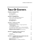
ORIGINAL INSTRUCTIONS TABLE OF CONTENTS CHAPTER 1: INTRODUCTION ISO Class 5 Definition About This Manual Typographical Conventions 1 2 2 3 CHAPTER 2: PREREQUISITES Support, Vibration & Movement Requirements Location and Air Current Requirements Airflow Specifications Electrical Requirements Space Requirements 5 5 6 6 7 7 CHAPTER 3: GETTING STARTED Unpacking the Clean Bench Installing Vertical Clean Bench on a Supporting Structure and Work Surface Verifying HEPA Filter Integrity Connecting Electrical Su
CHAPTER 6: MAINTAINING YOUR VERTICAL CLEAN BENCH Routine Maintenance Schedule When to Replace HEPA Filters How to Install a New HEPA Filter HEPA Filter Leak Test Setting the Downflow Velocity with Speed Control Adjustment Calibrate and Operate the Airflow Monitor Initial Certification Re-Certification Fluorescent Light Replacement UV Light Replacement (If equipped) Motorized Impeller Replacement Speed Control Replacement 25 26 26 27 29 30 31 34 34 34 34 35 37 CHAPTER 7: ACCESSORIZING & MODIFYING YOUR VERT
CHAPTER 1 INTRODUCTION Congratulations on your purchase of a Labconco Purifier® Vertical Clean Bench. Your enclosure provides product protection. It is the result of Labconco’s more than 30 years experience in manufacturing filtered enclosures. These enclosures will effectively provide product protection from airborne particulate matter. During operation, room air is drawn through the prefilter on top, forced through the blower and then through the HEPA filter and diffuser.
Chapter 1: Introduction ISO Class 5 Definition Airborne particulate cleanliness inside any clean bench or enclosure is designated by ISO Class 5, which is equivalent to 3520 particles 0.5 µm or larger per cubic meter of air per ISO Standard 14644-1. ISO Class 5 cleanliness is illustrated in the table to follow and is equivalent to Class 100 air conditions as defined by Federal Standard 209E. Class 100 is equal to 100 particles 0.5 µm or larger per cubic foot of air.
Chapter 1: Introduction Chapter 4: Performance Features and Safety Precautions explains how the Purifier Vertical Clean Bench operates and the appropriate precautions you should take when using it. Chapter 5: Appropriate Applications for your Vertical Clean Bench discusses the basic operation of how to prepare, use and shut down your Clean Bench. Chapter 6: Maintaining Your Vertical Clean Bench explains how to perform routine maintenance on the Clean Bench.
Chapter 1: Introduction 2' 3' Important information is presented in capitalized type in paragraphs that are preceded by the pointer icon. It is imperative that the information contained in these paragraphs be thoroughly read and understood by the user. A number icon precedes information that is specific to a particular model of enclosure. The 2' icon indicates the text is specific to the 2-foot wide model. The 3' icon indicates the text is specific to the 3-foot model, etc.
CHAPTER 2 PREREQUISITES Before you install the Vertical Clean Bench, you need to prepare your site for installation. You must be certain that the area is level and of solid construction. In addition, a dedicated source of electrical power should be located near the installation site to power the Clean Bench, and other apparatus. Additionally, the enclosure should be strategically placed in the lab to provide efficient workflow.
Chapter 2: Prerequisites Location and Air Current Requirements Purifier Vertical Clean Benches have been designed to provide particulate-free clean air meeting Class 5 conditions by negating typical cross drafts and turbulence within the opening. However, as a precautionary safety measure and a higher level of quality management, it is recommended that the clean bench be placed in an area away from: High traffic areas where walking might cause an air disturbance or be a nuisance.
Chapter 2: Prerequisites Electrical Requirements Standard duplex electrical receptacles should be nearby for connecting the Vertical Clean Bench, or other equipment. The enclosures include iris pass-throughs to allow electrical cords through the back of the enclosure without leaving a large hole. Space Requirements The dimensions for all the different models are shown in Appendix B: Dimensions.
CHAPTER 3 GETTING STARTED Now that the site for your Vertical Clean Bench is properly prepared, you are ready to unpack, inspect, install, and validate your Clean Bench. Read this chapter to learn how to: Unpack and move the Clean Bench. Set up the enclosure with the proper supporting structure and work surface. Verify HEPA filters integrity. Connect the electrical supply. Set the downflow velocity with the speed control adjustment. Validate enclosure airflow.
Chapter 3: Getting Started Unpacking the Clean Bench Carefully remove the shrink-wrap or carton on the Clean Bench and inspect it for damage that may have occurred in transit. If damaged, notify the delivery carrier immediately and retain the entire shipment intact for inspection by the carrier. DO NOT RETURN GOODS WITHOUT THE PRIOR AUTHORIZATION OF LABCONCO. UNAUTHORIZED RETURNS WILL NOT BE ACCEPTED. IF CLEAN BENCH WAS DAMAGED IN TRANSIT, YOU MUST FILE A CLAIM DIRECTLY WITH THE FREIGHT CARRIER.
Chapter 3: Getting Started Work Surface Specifications The work surface should be smooth, rigid and durable, such as a chemical-resistant epoxy resin. The surface should be non-porous and resistant to the materials used in conjunction with the Purifier Vertical Clean Bench. The work surface should also contain a dished recessed area for containing primary spills. Vertical Clean Bench Work Surface 1. Level the base cabinet or stand and the work surface. See Figure 3-1. 2.
Chapter 3: Getting Started Figure 3-1 Vertical Clean Bench Installation Product Service 1-800-522-7658 11
Chapter 3: Getting Started Verifying HEPA Filter Integrity The HEPA filter is shipped installed with the gasket on the downstream side. The HEPA filter is leak checked at Labconco. A second leak check is recommended before using the enclosure and at least annually thereafter. Consult your Safety Officer and Chapter 6 for the HEPA Filter Leak Test. See Figure 4-2 for HEPA filter location, HEPA filter gasket, and filter clamp bolts. All seams downstream of the HEPA filter are jacketed by positive pressure.
Chapter 3: Getting Started Setting the Downflow Velocity with the Speed Control Adjustment Adjustment of the speed control gives the correct downflow velocity and is located behind the front panel. The downflow velocity should be from 30-65 fpm for Class 100 (ISO class 5) conditions. ISO Class 5 clean air conditions are maximized at a setting within this range. The Vertical Clean Bench is factory set at 40-55 fpm downflow velocity.
Chapter 3: Getting Started The Purifier Vertical Clean Benches have been tested at Labconco before shipment and provide ISO Class 5 clean air conditions inside the enclosure. Labconco also performed extensive performance testing to validate the clean benches for product protection under ISO Class 5 conditions. For copies of these validation reports, contact Labconco Customer Service.
CHAPTER 4 PERFORMANCE FEATURES AND SAFETY PRECAUTIONS The Purifier Vertical Clean Bench is designed to provide product protection only from airborne particulate matter. During operation, room air is drawn from the top and filtered by the HEPA filter providing Class 5 conditions inside the enclosure. The Purifier Vertical Clean Bench delivers Class 5 air conditions when operating at downflow velocities of 30 to 65 feet per minute.
Chapter 4: Performance Features and Safety Precautions 6 10 12 9 Located Behind 4 2 5 8 Located Behind Control Panel 1 Figure 4-1 16 Product Service 1-800-522-7658
Chapter 4: Performance Features and Safety Precautions 19 7 Figure 4-2 Vertical Clean Bench Airflow Diagram 13 11 6 Airflow Switch with Adjustment Screw 15 Optional UV light (Not Shown) 18 4 1 17 Figure 4-2 Vertical Clean Bench Airflow Diagram Product Service 1-800-522-7658 17
Chapter 4: Performance Features and Safety Precautions 16 Figure 4-3 Optional UV Sash Closure 18 Product Service 1-800-522-7658
Chapter 4: Performance Features and Safety Precautions 1. Aerodynamic Lower Air Foil allows air to sweep the work surface and promote ISO Class 5 air conditions inside the enclosure. See Figure 4-1. 2. Ergonomic Slope of 10 degrees provides maximum visibility and comfort, reduces glare, thereby minimizing operator fatigue. See Figure 4-1. 3. Internal Depth of 25" provides necessary depth to work inside the enclosure. See Figure 4-1. 4.
Chapter 4: Performance Features and Safety Precautions 15. UV (Ultraviolet) Lamp (Not Shown), found only on some Clean Bench models, allows the operator to surface disinfect the work area of the enclosure when it is not in use. The UV light rays will not penetrate the plane of the sash and lower air foil. 16. UV Closure Panel provides protection when the UV lamp is on. The panel must be in place for the UV lamp to work. See Figure 4-3. 17.
Chapter 4: Performance Features and Safety Precautions 12. The HEPA filter provides Class 5 clean air conditions and only provides product protection inside the Clean Bench. Do not use the Clean Bench for personnel protection. 13. Never use flammable gases or solvents in the Clean Bench. Use of an open flame must be avoided in the Clean Bench. Open flames may disrupt the airflow patterns in the Clean Bench, burn the HEPA filter and damage the filter’s adhesive.
CHAPTER 5 APPROPRIATE APPLICATIONS FOR YOUR VERTICAL CLEAN BENCH Now that the installation of your Vertical Clean Bench is completed, you are ready to use it. Read this chapter to learn about: 1. Routine Daily Work Procedures. 2. Suitable Applications. 3. Appropriate HEPA Filter Applications, Suitability and Guidelines. Routine Daily Work Procedures Planning Arrange for minimal disruptions, such as room traffic or entry into the room while the Clean Bench is in use. Start-up Turn on blower and light.
Chapter 5: Appropriate Applications for Your Vertical Clean Bench Loading Materials and Equipment Load only the materials required for the procedure. Do not overload the Clean Bench. Do not obstruct the upper air diffuser screen. Large objects should not be placed close together. After loading, wait one minute to purge airborne contaminants from the work area. Work Techniques Keep all materials inside the lower air foil, and perform all operations as far to the rear of the work area as possible.
Chapter 5: Appropriate Applications for Your Vertical Clean Bench Listed below are suitable applications for HEPA filters. HEPA Filter Applications, Suitability and Guidelines 24 Procedures traditionally performed on an open bench where a clean Class 5 air environment is now required. The HEPA filtered enclosure provides product protection from particulate matter.
CHAPTER 6 MAINTAINING YOUR VERTICAL CLEAN BENCH Monitoring airflow and changing the filters are the primary maintenance required. Certification and recertification is also reviewed in Chapter 6. Review this chapter on maintenance for the following: 1. Routine Maintenance. 2. Determination of when to replace the HEPA filters. 3. How to install a new HEPA filter. 4. HEPA filter leak test. 5. Speed control adjustment and setting the downflow velocity. 6. Operating and calibrating the airflow monitors. 7.
Chapter 6: Maintaining Your Vertical Clean Bench Routine Maintenance Schedule Weekly Wipe down the interior surfaces of the enclosure with a disinfectant or cleaner, depending upon the usage of the unit and allow to dry. Using a damp cloth, clean the exterior surfaces of the enclosure, particularly the front and top to remove any accumulated dust. Operate the exhaust system, noting the airflow velocity out the front of the enclosure using a source of visible smoke.
Chapter 6: Maintaining Your Vertical Clean Bench How to Install a New HEPA Filter NOTE: Only a qualified certifier should service the HEPA filter. After the HEPA filter is replaced, the enclosure MUST be certified. See Figure 6-1. 1. Unplug the enclosure and remove the prefilter located on top. 2. Remove the front panel by loosening the two screws that secure it. 3. Using a 9/16" deep socket, loosen the filter clamp bolts located on top. Refer to Figure 6-1. 4.
Chapter 6: Maintaining Your Vertical Clean Bench Prefilter HEPA Filter HEPA Filter Sealing Surface Filter Clamp Bolt Gasket Side Down as Shown Gasket Front Panel Speed Control Adjustment Screw Figure 6-1 HEPA Filter Changing Diagram & Filter Leak Test Diagram 28 Product Service 1-800-522-7658
Chapter 6: Maintaining Your Vertical Clean Bench HEPA Filter Leak Test HEPA Purpose After installing the new HEPA filter, the HEPA filter should be leak checked. This test is performed to determine the integrity of the HEPA filter, the filter housing, and the filter seal. Leak testing must be done by a qualified technician with calibrated equipment. Remove the upper perforated diffuser located inside the enclosure by using a Phillips screwdriver to unfasten the screws. (See Figure 6-1).
Chapter 6: Maintaining Your Vertical Clean Bench 6. Set the valve to “DOWNSTREAM.” Place the palm of your hand over the sampling port of the pistol. There should be a strong vacuum at this port. If the vacuum is weak, contact Air Techniques Hamilton Associates. 7. Turn the enclosure on and let it operate for a minimum of 5 minutes. 8. If necessary, adjust the speed control of the enclosure to maintain the following downflow airflows at 55 fpm; 2' (230cfm), 3' (340 cfm), 4' (460 cfm.) 9.
Chapter 6: Maintaining Your Vertical Clean Bench Op t ion s Calibrate and Operate the Airflow Monitor Optional Guardian Airflow Monitor Refer to Figure 6-2 for operation and calibration. Labconco Airflow Monitor / Airflow Switch Operation The Guardian Airflow Monitor consists of a circuit board and an airflow switch. This switch indicates airflow as safe or low.
Chapter 6: Maintaining Your Vertical Clean Bench Calibration 1. Ensure the flow switch and alarm circuit board are installed and operational. 2. Allow the enclosure to operate for at least two minutes. 3. If factory installed, the monitor will alarm at 30±10 fpm downflow velocity with the average outflow velocity set at 85±10 fpm. 4. To change the factory setting, set the downflow velocity to the desired alarm condition using the speed control adjustment procedure outlined in Chapter 6.
Chapter 6: Maintaining Your Vertical Clean Bench Speed Control Light Reflector Airflow Monitor LED Circuit Board Airflow Switch with Adjustment Screw Control Panel Green “Safe” LED Silence Alarm Button with Test/Reset Red “Alert” LED with Audible Alarm Figure 6-2 Guardian Airflow Monitor with Airflow Switch Product Service 1-800-522-7658 33
Chapter 6: Maintaining Your Vertical Clean Bench Initial Certification The Purifier Vertical Clean Bench has been certified at the factory for an average downflow velocity of 40-55 fpm along with the HEPA Filter Leak Test. The Purifier Vertical Clean Bench should be certified for the proper downflow velocity required by your Safety Officer. It is also a conservative recommendation to perform the HEPA Filter Leak Test again should there be any damage caused during transport.
Chapter 6: Maintaining Your Vertical Clean Bench Motorized Impeller Replacement The motorized impeller must be replaced as a complete unit. When the motorized impeller is replaced, the capacitor should also be replaced. See Appendix A for Replacement Parts Diagram. See Figure 6-3 for an isometric view of the motorized impeller plenum assembly. The HEPA filter rests below the motorized impeller assembly. ! Do NOT contact blower wheel while still in motion.
Chapter 6: Maintaining Your Vertical Clean Bench Mounting Screws for Motorized Impeller 2' Model HEPA Filter Capacitor Mounted here on Electrical Subassembly Located behind the Control Panel Motorized Impeller Wire Access Hole Impeller Mounting Bracket Hardware Front Panel Wire Access Holes Motorized Impellers 3' or 4' Models Figure 6-3 Motorized Impeller Replacement 36 Product Service 1-800-522-7658
Chapter 6: Maintaining Your Vertical Clean Bench Speed Control Replacement 1. Remove the bracket that the speed control is attached to. See Figures 6-1 and 6-2. 2. Remove the two screws holding the speed control using a Phillips screwdriver. Refer to Appendix A for Replacement Parts Diagram. 3. Disconnect all wires leading to the speed control. Connect wires on new speed control in the same position as the old speed control. 4.
CHAPTER 7 ACCESSORIZING AND MODIFYING YOUR VERTICAL CLEAN BENCH There are several ways to accessorize and modify the Vertical Clean Bench for your individual requirements. These include the addition of accessory work surfaces, airflow monitors, filters, and storage cabinets or stands. 1. Work Surfaces An optional dished work surface is available to attach to the Vertical Clean Bench. Dished work surfaces are contoured to fit the dimensions of the filtered enclosures to contain spills.
Chapter 7: Accessorizing and Modifying Your Vertical Clean Bench 2. Guardian™ Airflow Monitor The Guardian Airflow Monitor allows you to continuously monitor airflow through the Clean Bench. The Guardian monitor can be placed on any Purifier Vertical Clean Bench. Description Guardian Airflow Monitor 115V or 230V 1 ea. 1 ea. 2 ea. Order Part #’s Individual Parts Required 3811500 3910700 Airflow Monitor Printed Circuit Board Airflow Sensor w/ Connector #6-32 x .
Chapter 7: Accessorizing and Modifying Your Vertical Clean Bench 4.
Chapter 7: Accessorizing and Modifying Your Vertical Clean Bench 5. IV Bar Kits For pharmacy applications, IV Bar Kits support intravenous bottles and bags.
CHAPTER 8 TROUBLESHOOTING AND SERVICER OPERATING LOG Refer to the following table if your Vertical Clean Bench fails to operate properly. If the suggested corrective actions do not solve your problem, contact Labconco for additional assistance. PROBLEM CAUSE CORRECTIVE ACTION Class 5 air conditions are not present inside the enclosure. Improper user techniques for the enclosure. See “Certifying the Enclosure” Chapter 3 and “Safety Precautions” Chapter 4 sections in the manual. (Ref. Appendix D).
Chapter 8: Troubleshooting and Servicer Operating Log PROBLEM Blower won’t operate. Poor internal Class 5 air conditions Blower and lights won’t operate. Light does not work. Airflow monitor malfunction. CAUSE Unit not plugged into outlet. Circuit breaker(s) or ground fault Interrupter. Blower wiring is disconnected. Blower switch is defective. Motorized impeller or blower is defective. Enclosure sash not closed. HEPA filter clogged. Unit not plugged into outlet. Circuit breaker(s) tripped.
Chapter 8: Troubleshooting and Servicer Operating Log PROBLEM Airflow monitor malfunction (Continued) CAUSE Wrong alarm set point. Constant audible alarm. Continuous alarm. Monitor alarms; air way to airflow monitor sensor is blocked by insects, dust or debris. Audible disable will not stay operational. 44 CORRECTIVE ACTION Airflow monitor was not properly adjusted. Repeat calibration steps outlined in this manual in Chapter 6. Check airflow and calibration of airflow monitor. See Chapter 6.
Chapter 8: Troubleshooting and Servicer Operating Log Service Operating Record Log Customer Name Model Number Date Installed Serial Number Unit Location Date Comments Product Service 1-800-522-7658 45
APPENDIX A VERTICAL CLEAN BENCH COMPONENTS AND REPLACEMENT PARTS The components that are available for your Vertical Clean Bench are listed. The parts shown are the most commonly requested. If other parts are required, please contact Product Service.
Appendix A: Components and Replacement Parts Item 1 2A 2B 2C 3A 3B 3C 4A 4B 4C 5A 5B 6 7A 7B 7C 7D 9A 9B 9C 10 11A 11B 12A 12B 12C 12D 12E 12F 12G 13A 13B 13C 13D 14A 14B 14C 15A 15B 16A 16B 16C Qty. 1 1 1 1 1 1 1 1 1 1 1 1 2 1 1 1 2 2 2 2 1.
Appendix A: Components and Replacement Parts Item 17A 17B 17C 17D 18A 18B 19 20A 20B 22A 22B 23A 23B 23C 23D 24A 24B 24C 24D 25A 25B 25C 25D 25E 25F 26A 26B 26C 27A 27B 27C 27D 28A 28B 29A 29B 29C 29D 29E 29F 30 31A 31B 31C Qty.
Appendix A: Components and Replacement Parts Item 32A 32B 32C 35A 35B 35C 35D 36A 36B 40A 40B 40C 40D 40E 41A 41B 41C 42 43 Qty. 1 1 1 1 1 1 1 1 - (115V) 2 - (230V) 1 1 2 2 2, 1" Long 1 1 1 2 1 Part Number 3707900 3707901 3707902 1333800 1305800 1305900 1339200 1327204 1327200 1952500 3667400 1905617 1551700 3788200 3560510 3560511 3560512 1907002 1322800 Product Service 1-800-522-7658 Description HEPA Filter (2') 18 x 18 x 3.32 w/ Gasket HEPA Filter (3') 30 x 18 x 3.
Appendix A: Components and Replacement Parts 24 26 Fluorescent 25 35, 36 Not Shown 27 UV 28 23 7 15 31 14 32 44 20 40 13 29 30 18 11 17 22 16 19 9 41 1 12, Not Shown 10 2 4 4 43, Not Shown 42 3 5 6 Figure A-1 Replacement Parts, Purifier Vertical Clean Benches 50 Product Service 1-800-522-7658
APPENDIX B DIMENSIONS See the following dimensions for the Purifier Vertical Clean Benches.
APPENDIX C VERTICAL CLEAN BENCH SPECIFICATIONS This Appendix contains technical information about all the Purifier Vertical Clean Benches including electrical specifications and environmental operating conditions. Electrical Specifications 5 Amps, 115V, 60 Hz 3 Amps, 230V, 50/60 Hz Environmental Conditions Indoor use only. Maximum altitude: 6562 feet (2000 meters). Ambient temperature range: 41° to 104°F (5° to 40°C).
APPENDIX D REFERENCES Many excellent reference texts and booklets are currently available. The following is a brief listing: Bryan, D., and R.C. Marback. 1984. Laminar-airflow equipment certification: What the Pharmacist needs to Know. American Journal of Hospital Pharmacy. 41.1343-1348. General Services Administration. 1988. FED-STD-209E Federal Standard – Clean Room and Work Station Requirements, Controlled Environment. Washington D.C. IES Recommended Practice: IES-RP-CC-001-86.