Original instructions User’s Manual Purifier® Horizontal Clean Benches Models 38897 Series, 3' 38884 Series, 4' 32500 Series, 5' 38730 Series, 6' 38185 Series, 8' To receive important product updates, complete your product registration card online at register.labconco.com Labconco Corporation 8811 Prospect Avenue Kansas City, MO 64132-2696 800-821-5525, 816-333-8811 FAX 816-363-0130 E-MAIL labconco@labconco.com HOME PAGE www.labconco.com Please read the User’s Manual before operating the equipment.
Original Instructions Copyright © 2009, 2010, 2011, 2012, 2013 Labconco Corporation. All rights reserved. The information contained in this manual and the accompanying products are copyrighted and all rights reserved by Labconco Corporation. Labconco Corporation reserves the right to make periodic design changes without obligation to notify any person or entity of such change. Warranty Labconco provides a warranty on all parts and factory workmanship.
Original Instructions TABLE OF CONTENTS CHAPTER 1: INTRODUCTION About This Manual Typographical Conventions 1 1 3 CHAPTER 2: PREREQUISITES Location Requirements Electrical Requirements Service Line Requirements Space Requirements Overhead Clearance 4 5 5 6 7 7 CHAPTER 3: GETTING STARTED Unpacking Your Clean Bench Clean Bench Components Removing the Shipping Skid Installing the Clean Bench on an Existing Work Surface Installing the Clean Bench on a Labconco Base Stand Telescoping Base Stands Initial Cer
Original Instructions CHAPTER 6: MAINTAINING YOUR CLEAN BENCH Routine Maintenance Schedule Service Operations Resetting the Circuit Breaker Changing the Prefilter Changing the Fluorescent Lamp Changing the UV Lamp Speed Control Adjustment Diffuser Removal HEPA Filter Replacement Motor/Blower Service Motor/Blower Replacement Adjusting the UV Shade Height Adjusting the UV Sensor Bracket Storage 24 25 26 26 26 27 27 27 29 29 30 31 31 32 33 CHAPTER 7: TROUBLESHOOTING 34 APPENDIX A: CLEAN BENCH COMPONENTS
Original Instructions CHAPTER 1 INTRODUCTION Congratulations on your purchase of a Labconco Purifier® Clean Bench. Your Clean Bench is designed to protect your product from particulate matter contamination. The Clean Bench offers many features to enhance safety, performance and ergonomics. To take full advantage of them, please acquaint yourself with this manual and keep it handy for future reference.
Chapter 1: Introduction Original Instructions Chapter 3: Getting Started contains the information you need to properly unpack, inspect, install, and certify your clean bench. Chapter 4: Theory Of Operation And Safety Precautions explains how the clean bench operates and the appropriate precautions you should take when using the bench. Chapter 5: Using Your Clean Bench discusses the basic operation of your bench. Information on how to prepare, use and shut down your clean bench is included.
Original Instructions Chapter 1: Introduction Typographical Conventions Recognizing the following typographical conventions will help you understand and use this manual: • • • • ! • • ) • Book, chapter, and section titles are shown in italic type (e.g., Chapter 3: Getting Started). Steps required to perform a task are presented in a numbered format. Comments located in the margins provide suggestions, reminders, and references.
Original Instructions CHAPTER 2 PREREQUISITES Before you install your clean bench, you need to prepare your site for installation. Carefully examine the location where you intend to install your bench. You must be certain that the area is level and of solid construction. In addition, a dedicated source of electrical power must be located near the installation site. Carefully read this chapter to learn: • • • • the location requirements for your installation site.
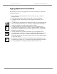
Chapter 2: Prerequisites Original Instructions Location Requirements ! ! The Purifier Clean Bench should be located away from traffic patterns, doors, fans, ventilation registers, fume hoods and any other air-handling device that could disrupt its airflow patterns. All windows in the room should be closed. Figure 2-1 shows the optimum location for the bench.
Chapter 2: Prerequisites Original Instructions Table 2-1 Model # Requirements Nominal Width 3889700, -01, -20, -21 3889702 to -12 & -22 to -32 3888400, -01, -20, -21 3888402 to -12 & -22 to -32 3250000, -01, -20, -21 3250002 to -12 & -22 to -32 3873000, -01, -20, -21 3873002 to -12 & -22 to -32 3818500, -01, -20, -21 3818502 to -12 & -22 to -32 115 VAC, 60 Hz, 7 Amps 230 VAC, 50/60 Hz, 4 Amps 115 VAC, 60 Hz, 7 Amps 230 VAC, 50/60 Hz, 4 Amps 115 VAC, 60 Hz, 10 Amps 230 VAC, 50/60 Hz, 5 Amps 115 VAC, 60
Original Instructions ! Chapter 2: Prerequisites L’utilisation de gaz inflammables ou de solvants dans l’hotte doit être évitée. Les flammes nues interromprent le circuit du courant d’air laminaire dans l’hotte. Si vous estimez que votre procedure exige l’utilisation d’une flamme nue ou des matériaux inflammables, Prenez contact avec un officiel de sécurité competent.
Original Instructions CHAPTER 3 GETTING STARTED Now that the site for your clean bench is properly prepared, you are ready to unpack, inspect, install, and certify your unit. Read this chapter to learn how to: • • • • • unpack and move your bench. set up the bench. connect the electrical supply source. connect the service lines. arrange certification of your Purifier Horizontal Clean Bench.
Chapter 3: Getting Started Original Instructions Unpacking Your Clean Bench Carefully unpack your Purifier Clean Bench and inspect it for damage that may The United States Interstate have occurred in transit. If your unit is damaged, notify the delivery carrier Commerce immediately and retain the entire shipment intact for inspection by the carrier. Commission rules require DO NOT RETURN GOODS WITHOUT THE PRIOR that claims be AUTHORIZATION OF YOUR DEALER AND LABCONCO.
Chapter 3: Getting Started Original Instructions Plus the Following: Part # Component Description 3876800 1337100 User’s Manual Power Cord, 115V Or (one of the following) Power Cord, 230V United States Power Cord, 230V United Kingdom Power Cord, 230V Schuko Power Cord, 230V China/Australia 1338000 1332600 1336100 1332700 If you did not receive one or more of the components listed for your clean bench, or if any of the components are damaged, contact the Labconco Product Service Department immediately
Original Instructions Chapter 3: Getting Started Figure 3-1 Installing the Purifier Clean Bench On An Existing Work Surface ! The clean bench is very top heavy! Use caution when lifting or moving the unit. ! L’hotte est très lourde du haut! Soulever ou déplacer l’appareil avec précaution. When installing the clean bench onto an existing work surface or benchtop, ensure that the structure can safely support the combined weight of the bench and any related equipment.
Chapter 3: Getting Started Original Instructions Installing the Purifier Clean Bench on a Labconco Base Stand Labconco offers a variety of accessory base stands in a number of different configurations to suit your particular needs. Stands can be ordered with preset telescoping legs, or with a manually or electrically adjustable variable height stand. Telescoping Base Stands These stands are available with either fixed feet or caster wheels.
Chapter 3: Getting Started Original Instructions 2. Select the height of the Telescoping Base Stand and slide four (4) leg extensions into base stand corner posts and attach with 2.25" long bolt, flatwasher, lockwasher and nut. Ensure that the same height hole is selected for each leg. Tighten the leg bolts securely. See Figure 3-2. Figure 3-2 3. Move the base stand into its final location.
Chapter 3: Getting Started Original Instructions ! The clean bench is very top heavy! Use caution when lifting or moving it. ! L’hotte est très lourde du haut! Soulever ou déplacer avec précaution. 4. Carefully lift the clean bench onto the top rails of the base stand and slide it into position. The rear of the bench should be flush with the rear of the base stand and the sides of the clean bench will overhang the side rails of the base stand approximately 0.25 inches on both sides. 5. Insert the 2.
Original Instructions CHAPTER 4 THEORY OF OPERATION AND SAFETY PRECAUTIONS All clean benches operate using the following principles: • • Filtration and retention of particulates by High Efficiency Particulate Air (HEPA) filter(s) Laminar airflow The major components in a clean bench are: • • • The HEPA filter The motor/blower to force air through the unit A speed control for the motor HEPA Filters HEPA filters are disposable, dry-type particulate filters.
Chapter 4: Theory of Operation and Safety Precautions Original Instructions HEPA Filters are only effective against particulate material. Gases will pass through the filter. ! Le matériel du filtre HEPA est très fragile. Ne pas toucher ou être en contact avec la surface du matériel. Si vous pensez que la surface d’un filter HEPA est endommagé, NE PAS UTILISER L’HOTTE. Faire tester l’intégrité du filter HEPA par un certificateur qualifié avant d’utiliser l’hotte.
Original Instructions Chapter 4: Theory of Operation and Safety Precautions Laminar Airflow Laminar airflow is defined as the movement of a body of air in a single direction, with a uniform velocity. In practice, the horizontal laminar flow of sterile air in the clean bench flushes out any aerosol generated in the work area of the bench. This sterile airflow maintains the sterility of sterile items inside the clean bench.
Chapter 4: Theory of Operation and Safety Precautions Original Instructions Speed Control ! The speed control should only be adjusted by a qualified certifier. ! Le contrôle de la vitesse doit être réglée uniquement par un certificateur qualifié. The speed control is an electronic circuit that allows the certifier to set the motor speed by adjusting its voltage. ! Never block or obstruct the air intake on the top of the clean bench. ! Ne jamais bloquer l’entrée d’air au dessus de l’hotte.
Original Instructions Chapter 4: Theory of Operation and Safety Precautions unit is connected to electrical service in accordance with local and national electrical codes. Failure to do so may create a fire or electrical hazard. Do not remove or service any electrical components without first disconnecting the clean bench from electrical service. Le Purifier Clean Bench doit être certifié par un technician de certification qualifié avant la première utilization.
Chapter 4: Theory of Operation and Safety Precautions Original Instructions THE HEPA FILTER IN THE PURIFIER CLEAN BENCH WILL GRADUALLY ACCUMULATE AIRBORNE PARTICULATE MATTER FROM THE ROOM. THE RATE OF ACCUMULATION WILL DEPEND UPON THE CLEANLINESS OF THE ROOM AIR, THE AMOUNT OF TIME THE CLEAN BENCH IS OPERATING AND THE NATURE OF WORK BEING DONE IN THE CLEAN BENCH. IN TYPICAL INSTALLATIONS AND USAGE, THE HEPA FILTERS WILL LAST TWO TO FIVE YEARS BEFORE REQUIRING REPLACEMENT.
Original Instructions CHAPTER 5 USING YOUR CLEAN BENCH Starting the Clean Bench To start the Clean Bench, push the blower switch to the “ON” position, as shown in Figure 5-1. Operating the Fluorescent Light To turn on the fluorescent light, push the light switch to the “ON” position, as shown in Figure 5-1.
Chapter 5: Using Your Clean Bench Original Instructions Reading the Pressure Gauge The pressure gauge on the front of the unit displays the total system operating pressure (the negative pressure below the prefilters, plus the positive pressure on the HEPA filter). The pressure gauge reading should be periodically recorded during use. An increase in pressure from the original pressure reading indicates either prefilter or HEPA filter loading.
Original Instructions • • • Chapter 5: Using Your Clean Bench Avoid the use of an open flame. Use proper aseptic technique. – “Sterile Air First” Avoid using techniques or procedures that disrupt the airflow patterns of the clean bench. Final Purging • Upon completion of work, the clean bench should be allowed to operate for 2 to 3 minutes undisturbed, to purge airborne contaminants from the work area.
Original Instructions CHAPTER 6 MAINTAINING YOUR CLEAN BENCH Now that you have an understanding of how to work in the clean bench, we will review the suggested maintenance schedule and the common service operations necessary to maintain your clean bench for peak performance. ! ! 24 Many of the service operations should be performed only by trained and experienced certification technicians. DO NOT attempt to perform these operations if you are not properly trained.
Original Instructions Chapter 6: Maintaining Your Clean Bench Routine Maintenance Schedule Under normal operation, your Purifier Horizontal Clean Bench will require little routine maintenance. The following schedule is recommended: Weekly • Wipe down the interior surfaces of the clean bench with stainless steel cleaner or 70% ethanol and allow to dry. • Using a damp cloth, clean the exterior surfaces of the clean bench, particularly the front and top of the clean bench to remove any accumulated dust.
Chapter 6: Maintaining Your Clean Bench Original Instructions Service Operations Resetting the Circuit Breaker: 1. The circuit breaker is located next to the power cord on the upper rear panel of the bench as shown in Figure 6-1. If the circuit breaker trips, it can be reset by pressing the white button in. Figure 6-1 Prefilter Retainers Loosen and remove both screws to remove each retainer.
Original Instructions Chapter 6: Maintaining Your Clean Bench Changing the Fluorescent Lamp: 1. Unplug the Purifier Clean Bench. 2. Remove the prefilters as described earlier in this chapter. 3. Remove the front dress panel by removing the four screws located on the top front corners of the panel, and then lifting the panel up and forward. 4. Remove the lamp reflector by gently squeezing the reflector to compress it and then lift the reflector straight up. 5.
Chapter 6: Maintaining Your Clean Bench Original Instructions 1. Remove the prefilters as described on page 24. 2. Locate the speed control. It is to the left of the blower on 3-foot and 4-foot models, and between the blowers on the 5-foot, 6-foot & 8-foot models. 3. Using a medium-sized, straight blade screwdriver turn the speed control screw clockwise to decrease the blower speed as shown in Figure 6-2. Figure 6-2 4.
Chapter 6: Maintaining Your Clean Bench Original Instructions Diffuser Removal: 1. Locate and remove the diffuser screws, shown in Figure 6-3. Pull the diffuser straight out. Figure 6-3 HEPA Filter Replacement: The HEPA filter should only be serviced by a qualified certification technician. Following replacement of the HEPA filter, a qualified certification technician MUST recertify the clean bench. 1. Unplug the clean bench. 2. Remove the diffuser as described above. 3.
Chapter 6: Maintaining Your Clean Bench Original Instructions Figure 6-4 5. Remove the filter by pulling it straight out of the Purifier. 6. Install the new filter by placing the filter back into the clean bench. Make sure that the HEPA filter is centered side-to-side in the Purifier. Reinstall the stainless steel plates on the HEPA filter frame. 7. Install the secondary HEPA filter seal, ensuring that the seal is in place completely around the sides and top of the filter frame. 8.
Original Instructions Chapter 6: Maintaining Your Clean Bench Motor/Blower Replacement: ) ! A QUALIFIED CERTIFICATION TECHNICIAN SHOULD SERVICE THE MOTOR/BLOWER. FOLLOWING REPLACEMENT OF A MOTOR/BLOWER, A QUALIFIED CERTIFICATION TECHNICIAN MUST RECERTIFY THE CLEAN BENCH. Do NOT contact blower wheel while still in motion. NE PAS être en contact avec la roué du ventilateur tant qu’il est en marche. 1. Unplug the clean bench. 2. Remove the prefilters, as described earlier. 3.
Chapter 6: Maintaining Your Clean Bench Original Instructions 5. A finer adjustment can be made to the shade closing height by backing the two torx head (T20) screws out one or two turns on each of the UV Shade support brackets, in order to allow the support brackets to slide up or down one hole notch on the brackets. The UV Shade Cover does not need to be removed for this adjustment.
Original Instructions Chapter 6: Maintaining Your Clean Bench 2. Look to see how far away from the UV Lockout Sensor the Sensor Bracket is, it should be approximately ¼” (6 mm) or closer to the white, round, Lockout Sensor in the Stainless Steel Worksurface. 3. Turn on the UV Light as described in Chapter 5, Section Operating the UV Light.
Original Instructions CHAPTER 7 TROUBLESHOOTING Refer to the following table if your Purifier Clean Bench fails to operate properly. If the suggested corrective actions do not solve your problem, contact Labconco Product Service for additional assistance. PROBLEM CAUSE CORRECTIVE ACTION Blower and lights won’t turn on Unit not plugged into outlet Plug the clean bench into appropriate electrical service. Circuit breakers tripped Reset circuit breakers.
Chapter 7: Troubleshooting Original Instructions PROBLEM CAUSE CORRECTIVE ACTION Contamination of work in the clean bench (cont.) External factors are disrupting the clean bench airflow patterns or acting as a source of contamination See “Installation” section of this manual. Clean bench is out of adjustment/HEPA filter(s) are defective Have clean bench recertified. Motor/blower out of adjustment Application requires equipment isolation Accessory vibration table.
Original Instructions APPENDIX A CLEAN BENCH COMPONENTS Illustration A-1 indicates the location of the following service parts: Purifier Horizontal Clean Bench Replacement Parts Item 1 1A 1B 1C 1D 2 2A 2B 2C 2D 2E 2F 3 3A 3B 3C 3D 3E 4 4A 4B 4C 5* 5A* 6 6A 7 7A 7B 7C Quantity Part No.
Original Instructions Appendix A: Clean Bench Components A-1 5* Product Service 1-800-522-7658 37
Original Instructions APPENDIX B DIMENSIONS B-1 3-foot DEPTH “A”** “B” “C” 21.0 38.0 37.0 34.0 26.0 38.0 37.0 39.0 4-foot 21.0 50.0 49.0 34.0 26.0 50.0 49.0 39.0 5-foot 21.0 62.0 61.0 34.0 26.0 62.0 61.0 39.0 6-foot 21.0 74.0 73.0 34.0 26.0 74.0 73.0 39.0 8-foot 21.0 99.0 98.1 34.0 **For models with UV option, add 1.0" to overall width. 38 Product Service 1-800-522-7658 26.0 99.0 98.1 39.
Original Instructions APPENDIX C CLEAN BENCH SPECIFICATIONS Electrical Data Bench Model 3889700, -01, -20, -21 (3-foot) 3888400, -01, -20, -21 (4-foot) 3250000, -01, -20, -21 (5-foot) 3873000, -01, -20, -21 (6-foot) 3818500, -01, -20, -21 (8-foot) Electrical Requirements 115 VAC – 60 Hz, 1 Phase – 7 Amps 115 VAC – 60 Hz, 1 Phase – 7 Amps 115 VAC – 60 Hz, 1 Phase – 10 Amps 115 VAC – 60 Hz, 1 Phase – 10 Amps 115 VAC – 60 Hz, 1 Phase – 12 Amps Bench Model 3889702 to -12 & -22 to -32 (3-foot) 3888402 to -12
Appendix C: Clean Bench Specifications Original Instructions Environmental Conditions • • • • • • • 40 Indoor use only. Maximum altitude: 6562 feet (2000 meters). Ambient temperature range: 41° to 104°F (5° to 40°C). Maximum relative humidity: 80% for temperatures up to 88°F (31°C), decreasing linearly to 50% relative humidity at 104°F (40°C). Main supply voltage fluctuations not to exceed ±10% of the nominal voltage.
Original Instructions Appendix C: Clean Bench Specifications C-1 C-2 Product Service 1-800-522-7658 41
Appendix C: Clean Bench Specifications Original Instructions C-2 C-3 42 Product Service 1-800-522-7658
Original Instructions Appendix C: Clean Bench Specifications C-4 C-5 Product Service 1-800-522-7658 43
Appendix C: Clean Bench Specifications Original Instructions C-6 44 Product Service 1-800-522-7658
Original Instructions Appendix C: Clean Bench Specifications C-7 Product Service 1-800-522-7658 45
Original Instructions APPENDIX D CLEAN BENCH ACCESSORIES Telescoping Base Stands Epoxy-coated steel, height can be set at 27.5 to 34.5 inches in 1-inch intervals, giving a work surface height of 28.75 to 35.75 inches. Model # w/feet 3613200 3888700 3255000 3857700 3857300 Model # w/wheels 3613201 3888701 3255001 3857701 3857301 For use with 3-foot Purifier Clean Bench 4-foot Purifier Clean Bench 5-foot Purifier Clean Bench 6-foot Purifier Clean Bench 8-foot Purifier Clean Bench Shipping Weight 95 lbs.
Appendix D: Clean Bench Accessories Original Instructions Vibration Isolation Table (#3618000) Provides an isolated work surface for conducting procedures with vibrationsensitive equipment such as microscopes and balances. The table never makes contact with the clean bench so vibration from the motor/blower is not transmitted to the table. Epoxy-coated steel frame, adjust in 1" increments to provide a working height from 29.5 to 36". ADA-compliant. Four leveling feet.
Original Instructions APPENDIX E QUICK CHART FOR PURIFIER HORIZONTAL CLEAN BENCHES Width (feet) HEPA Filter Dims. (in.) Avg. Velocity Reading Grid (inches) Grid Distance from Diffuser (inches) Grid Distance from Sidewalls (inches) Average Velocity (FPM) Work Area (ft2) Exhaust Volume Range (CFM) Number of Laskin Nozzles needed 3 36 x 30 x 3 12 x 12 6 6 90 ±10 7.5 600-750 2 4 48 x 30 x 3 12 x 12 6 6 90 ±10 10 800-1000 2 5 60 x 30 x 3 12 x 12 6 6 90 ±10 12.
Original Instructions Product Service 1-800-522-7658 49