User’s Manual Protector® XL™ Floor-Mounted (Walk-In) Laboratory Fume Hoods Models 97008 Series 97009 Series 97010 Series 97160 Series 98604 Series 98605 Series 98606 Series To receive important product updates, complete your product registration card online at register.labconco.com Labconco Corporation 8811 Prospect Avenue Kansas City, MO 64132-2696 800-821-5525, 816-333-8811 FAX 816-363-0130 E-MAIL labconco@labconco.com HOME PAGE www.labconco.
Copyright © 2002, 2007 Labconco Corporation. All rights reserved. The information contained in this manual and the accompanying products are copyrighted and all rights reserved by Labconco Corporation. Labconco Corporation reserves the right to make periodic design changes without obligation to notify any person or entity of such change. Warranty Labconco provides a warranty on all parts and factory workmanship.
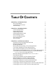
TABLE OF CONTENTS CHAPTER 1: INTRODUCTION About This Manual Typographical Conventions Your Next Step 1 2 3 4 CHAPTER 2: PREREQUISITES Location Requirements Support Requirements Exhaust Requirements Exhaust Requirements Table Electrical Requirements Service Line Requirements Space Requirements Your Next Step 7 8 8 8 9 10 10 10 10 CHAPTER 3: GETTING STARTED Unpacking Your Floor-Mounted Fume Hood Removing the Shipping Skid Sash Weight Release Disassembly & Reassembly of Floor-Mounted Hood Lower Base Instal
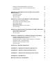
Sealing the Floor-Mounted Hood to the Floor Certifying the Protector XL Floor-Mounted Hoods Your Next Step 29 29 30 CHAPTER 4: PERFORMANCE FEATURES AND SAFETY PRECAUTIONS Performance Features Safety Precautions Your Next Step 31 31 35 37 CHAPTER 5: USING YOUR PROTECTOR FUME HOOD Operating the Vertical-Rising Sash Operating the Horizontal-Sliding Sashes Operating the Blower Operating the Lights Working in your Protector Fume Hood Your Next Step 39 39 40 40 40 40 42 CHAPTER 6: MAINTAINING YOUR PROTECTOR
CHAPTER 1 INTRODUCTION Congratulations on your purchase of a Labconco Protector® XL™ Floor-Mounted (Walk-In) Laboratory Fume Hood. Your Protector Floor-Mounted Laboratory Fume Hood is designed to protect you. It is the result of Labconco’s more than 50 years experience in manufacturing fume hoods, and users like you suggested many of its features to us.
Chapter 1: Introduction About This Manual This manual is designed to help you learn how to install, use, and maintain your laboratory fume hood. Instructions for installing optional equipment on your hood are also included. Chapter 1: Introduction provides a brief overview of the Floor-Mounted (Walk-In) Laboratory Fume Hood, explains the organization of the manual, and defines the typographical conventions used in the manual.
Chapter 1: Introduction Appendix A: Protector XL Floor-Mounted Hood Components contains labeled diagrams of all of the components of the fume hoods. Appendix B: Protector XL Floor-Mounted Hood Dimensions contains comprehensive diagrams showing all of the dimensions for the laboratory fume hoods. Appendix C: Protector XL Floor-Mounted Hood Specifications contains the electrical requirements for laboratory fume hood. Wiring diagrams are also included.
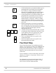
Chapter 1: Introduction • ! • ) 4' 5' • 6' • V • 8' H • Critical information is presented in boldface type in paragraphs that are preceded by the exclamation icon. Failure to comply with the information following an exclamation icon may result in injury to the user or permanent damage to fume hood. Critical information is presented in boldface type in paragraphs that are preceded by the wrench icon. These operations should only be performed by a trained certifier or contractor.
Chapter 1: Introduction If your laboratory fume hood is installed and you need to perform routine maintenance on the cabinet, proceed to Chapter 6: Maintaining Your Protector XL FloorMounted Hood. For information on making modifications to the configuration of your fume hood, go to Chapter 7: Modifying Your Protector XL Floor-Mounted Fume Hood. Refer to Chapter 8: Troubleshooting if you are experiencing problems with your fume hood.
Chapter 1: Introduction 6 Product Service 1-800-522-7658
CHAPTER 2 PREREQUISITES Before you install your Protector XL Floor-Mounted Hood, you need to prepare your site for installation. Carefully examine the location where you intend to install your floor-mounted hood. You must be certain that the area is level and of solid construction. In addition, a dedicated source of electrical power must be located near the installation site. Carefully read this chapter to learn the requirements for your installation site: • • • • • • The location requirements.
Chapter 2: Prerequisites Location Requirements ! The floor-mounted fume hood should be located away from traffic patterns, doors, windows, fans, ventilation registers, and any other air-handling device that could disrupt its airflow patterns. All windows in the room should be closed. Support Requirements ! DO NOT install the floor-mounted fume hood on a cart, dolly, or mobile bench. ALL Protector XL FloorMounted Hood installations must be permanent and stationary.
Chapter 2: Prerequisites Hood Size Standard Model Description 4' Vertical 48" Protector XL Floor-Mounted (Walk-In) Hood 5' Vertical 60" Protector XL Floor-Mounted (Walk-In) Hood 6' Vertical 72" Protector XL Floor-Mounted (Walk-In) Hood 8' Vertical 96" Protector XL Floor-Mounted (Walk-In) Hood with Vertical-Rising Sashes 8' Horizontal 96" Protector XL Floor-Mounted (Walk-In) Hood with horizontal-sliding sashes 120" Protector XL Floor-Mounted (Walk-In) Hood with horizontal-sliding sashes 144" Prot
Chapter 2: Prerequisites Electrical Requirements The Protector XL Floor-Mounted Hood models feature internal wiring for the fluorescent light assembly and light switch. All internal wiring is terminated at the single point wiring junction box for hook-up by a qualified electrician. The blower switch and light switch wires are also terminated at the single point wiring junction box for hook-up by a qualified electrician.
CHAPTER 3 GETTING STARTED Now that the site for your Protector XL Floor-Mounted (Walk-In) Hood is properly prepared, you are ready to unpack, inspect, install, and certify it. Read this chapter to learn how to: • Unpack and move your Protector XL FloorMounted Hood. • Set up the floor-mounted fume hood on the floor. • Connect to an exhaust system. • Connect the electrical supply source. • Connect the service lines. • Sealing the Protector Hood to the floor. • Arrange certification of your Protector Hood.
Chapter 3: Getting Started Unpacking Your Protector XL Floor-Mounted Fume Hood Your Protector XL Floor-Mounted (Walk-In) Hood has been shipped to you as ten main component assemblies located on three shipping skids. The ten main component assemblies consist of the lower base, upper cabinet, sashes, lower sash track, corner posts, service fixtures, electrical connections, baffles, header, and front panel.
Chapter 3: Getting Started Do not move the hood by tilting it onto a hand truck. ! Removing the Shipping Skid ) LEAVE THE FUME HOOD ATTACHED TO ITS SHIPPING SKID UNTIL IT IS AS CLOSE TO ITS FINAL LOCATION AS POSSIBLE. MOVE THE HOOD BY USING A SUITABLE FLOOR JACK, OR BY PLACING A FURNITURE DOLLY UNDERDNEATH THE SKID. DO NOT MOVE THE HOOD BY TILTING IT ONTO A HAND TRUCK. After you verify the fume hood components, move your hood to the location where you want to install it.
Chapter 3: Getting Started ) NOTE: THE SASH WEIGHT IS MATCHED FOR THIS MODEL OF HOOD AND SHOULD NOT BE EXCHANGED WITH ANY OTHER UNIT. Disassembly and Reassembly of the Protector XL Floor-Mounted Hood There may be some disassembly and reassembly work, due to the large physical size of your laboratory hood and the ability to maneuver it into your laboratory. This is specific to each customer.
Chapter 3: Getting Started Upper Cabinet Installation of the Protector XL FloorMounted Hood Remove the upper cabinet assembly side panels and front panels prior to cabinet placement. Then place the upper cabinet assembly on top of the lower base assembly, being careful to clear the lower base assembly during placement. To prevent spillage from seeping between the two liner assemblies, run a bead of white RTV sealant between the sections once they have been properly aligned.
Chapter 3: Getting Started Vertical-Rising Sash Installation for the 4', 5', 6', & 8' Floor-Mounted Hoods V The Vertical-Rising Sash Floor-Mounted Hood has two vertical-rising sashes. The rear vertical-rising sash moves from the floor to full open and picks up the front vertical-rising sash, which travels from the midpoint to full open. The sash tracks should be adjusted left to right to assure the sash will work properly.
Chapter 3: Getting Started Rear Lower Sash attaches to Outer Cable to Outer two Weights for full travel Front Upper Sash attaches to Inner Cable to Inner Sheet Metal Weight for partial upper travel only Inner Rear Pulley Inner Front Pulley for Front Upper Sash Outer Rear Sheave Location of selfdrilling screws to mount corner posts Outer Front Pulley for Rear Lower Sash Left Corner Post is removed to show Dual Sash Track Rear Weight Track & #10-24 Flathead Screw & #10-24 KEPS Nut Front Upper Sash
Chapter 3: Getting Started Left Corner Post Typical Stainless Steel Corner Post Screws. Strap Plate Strap Plate Hardware Right Corner Post Upper Front Sash Rubber Bumper Align Upper and Lower Sash Tracks with Strap Plates (both sides).
Chapter 3: Getting Started Left Sash Weight for Rear Sash that travels to the floor Sheet Metal Sash Weight for Upper Front Sash Right Sash Weight Left Rear Sash Track (other side not shown) Rear View Figure 3-4 Product Service 1-800-522-7658 19
Chapter 3: Getting Started Lower Sash Track & Threshold Installation for Horizontal-Sliding Sashes on 8', 10', 12', & 16' FloorMounted Hoods H 20 The lower sash track assembly is comprised of a sash track threshold, front and rear ramps, and threshold support brackets. With the corner posts removed the sash track threshold should be placed on the floor between the left and right corner posts, with their corner posts removed at this time. Lay the threshold flat, perpendicular to the hood liner walls.
Chapter 3: Getting Started Threshold Support Bracket Rear Ramp Lower Sash Track Threshold Front Ramp Figure 3-5 Horizontal-Sliding Sash Installation for the 8', 10', 12', & 16' Floor-Mounted Hoods The Floor-Mounted Hood with horizontal-sliding sashes is supplied with four individual sash doors. These doors have been packaged separately during shipment and require installation in the field. The doors should not be installed until the lower sash track threshold has been properly installed.
Chapter 3: Getting Started the door assembly into the corresponding lower track slot. As each door is placed into position, slide the door the full length of the track assembly to assure proper height adjustment. If the door drags in the lower track, adjust the nylon roller bearing on the mounting bracket to raise the height of the door. Reverse the movement of the bearing should the door assembly be too short and not fit in the lower track properly.
Chapter 3: Getting Started Corner Post Installation for the Floor-Mounted Hoods Both left and right corner posts have been shipped uninstalled. The one-piece corner posts are to be installed once the upper and lower cabinet assemblies have been properly positioned. The edges on the corner posts fit directly onto the side frames. The front inner edge of both corner posts are held in place by stainless steel machine screws.
Chapter 3: Getting Started Figure 3-7 24 Product Service 1-800-522-7658
Chapter 3: Getting Started Header Installation for the Floor-Mounted Hoods The header is shipped separately in its protective packaging. To install, the header is fastened to the corner covers by four #12 screws. Reach behind the corner posts from the side and install the screws to support the header. See Figure 3-8. #12 Screws Corner Post Header Figure 3-8 Front Panel Installation for the Floor-Mounted Hoods The hood front panel(s) is shipped separately and is protected.
Chapter 3: Getting Started Connecting to the Protector Hood Exhaust System ! WARNING: The weight of the exhaust ductwork system must be supported independently of the hood superstructure. Do not allow this weight to be supported by the hood structure as damage to the hood may occur. The exhaust connection should be installed by a qualified HVAC contractor. The exhaust connections on your hood has been designed for 12" nominal pipe (12.
Chapter 3: Getting Started The identification plate, model number, serial number, and electrical connection boxes are accessible from the front of the fume hood by removing the front panel. The Protector XL Floor-Mounted Hood is normally wired for 115 Volt, 60 Hz, 20 Amp or 230 Volt, 50 Hz, 10 Amp electrical service. Check the I.D. plate behind the front panel for voltage verification. The number of circuits varies depending on the model.
Chapter 3: Getting Started grounding connection shall not be made to the terminal box cover. The fluorescent light has been mounted outside the top liner panel and is sealed from vapors inside the hood structure. To change the fluorescent light bulbs in your hood, you must first remove the front panel from the hood. Next remove the knock out plugs holding the light fixture in place. Lift fixture up and replace any defective bulbs. Reverse order to reassemble.
Chapter 3: Getting Started ! WARNING: Contact Labconco Customer Service before using any service other than those listed above in these valves to assure full compatibility. ! CAUTION: Natural gas should be used only in the service fixture that has been pre-plumbed with brass tubing. Sulfur content of the gas could cause deterioration of standard copper supply lines.
Chapter 3: Getting Started Ventilation Ventures Team or Customer Service for a certified on-site contractor. ! NOTE: Face velocity profiles and smoke testing should be done periodically to ensure safe performance. Your Next Step After your fume hood has been installed and certified, you are ready to proceed to Chapter 4: Performance Features and Safety Precautions.
CHAPTER 4 PERFORMANCE FEATURES AND SAFETY PRECAUTIONS Performance Features: The Protector XL Floor-Mounted Laboratory Hood is designed to meet the needs of the laboratory scientist who must transport equipment and products for experimentation, and testing under a laboratory fume hood. The Floor-Mounted Fume Hood has been designed to effectively contain toxic, noxious, or other harmful materials when properly installed.
Chapter 4: Performance Features and Safety Precautions 1. Unique sash provides maximum visibility. Vertical-rising sashes may be raised from a closed to 58.81" operating height; this feature is available on 4', 5', 6', and 8' floor mount models. Exhaust volume, and blower sizing is based on the rear sash being closed and the front sash opened.
Chapter 4: Performance Features and Safety Precautions 9. Streamlined corner posts provide maximum visibility and the flexibility to add services after installation. 10. All hoods are factory-prepared for up to 8 service fixtures. 11. Duplex electrical receptacles are mounted on the right and left corner posts as requested. Receptacles are factory-wired to hood single point junction box. 12. Accessory Guardian™ Digital Airflow Monitor or Guardian Jr. Monitor continuously monitors face velocity.
Chapter 4: Performance Features and Safety Precautions 13 6 14 9 7 10 5 12 11 1 2 8 Figure 4-1 34 Product Service 1-800-522-7658
Chapter 4: Performance Features and Safety Precautions Safety Precautions ! ) Although the floor-mounted laboratory hood has been engineered to maintain optimum operator safety, caution should always be used while working in the hood. Prior to using the floormounted hood, check to make sure that the exhaust blower is operating and that air is entering the hood at its specified face velocity. USE GOOD HOUSEKEEPING IN THE HOOD AT ALL TIMES. CLEAN UP SPILLS IMMEDIATELY WITH A MILD DETERGENT.
Chapter 4: Performance Features and Safety Precautions ! Blocking the bottom of the baffle at rear of hood will change the airflow pattern in the hood causing turbulence and possible leakage at the face of the hood. (Don’t store containers or supplies against baffles, as this will affect airflow through the hood). Avoid placing your head inside hood. Keep hands out of hood as much as possible. Always work as far back in hood as possible.
Chapter 4: Performance Features and Safety Precautions ) ! AVOID CROSS DRAFTS AND LIMIT TRAFFIC IN FRONT OF THE HOOD. AIR DISTURBANCES CREATED MAY DRAW FUMES OUT OF THE HOOD. The use of heat generating equipment in this hood without the exhaust system operating properly can cause damage to the hood. The Protector XL Floor-Mounted Hood should be certified by a qualified certification technician before it is initially used.
Chapter 4: Performance Features and Safety Precautions 38 Product Service 1-800-522-7658
CHAPTER 5 USING YOUR PROTECTOR XL FLOOR-MOUNTED FUME HOOD Operating the VerticalRising Sashes 4' 5' 6' 8' V Because of the Protector XL Floor-Mounted Hood counterbalanced sash mechanism, it will take only a few pounds of force to move the sashes up or down, and you can operate the sash smoothly with one or two hands positioned any where along the handle. The vertical-rising sash may be raised to a maximum 58.81" operating height from the floor.
Chapter 5: Using Your Protector Fume Hood 8' 10' 12' 16' H 4' 5' 10' 4' 5' 10' Operating the HorizontalSliding Sashes Horizontal-sliding sashes allow the operator the flexibility of arranging the sashes at a position suitable for various procedures. The glass sashes have a 68.15" sash opening providing a large viewing area. The airflow requirements are sized for the 50% open sash condition for the 8' model and 25% for the 10', 12', and 16' models.
Chapter 5: Using Your Protector Fume Hood • Wear a long sleeved lab coat and rubber gloves. Use protective eyewear. Wear a protective mask if appropriate. Loading Materials and Equipment • Only load the materials required for the procedure. Do not overload the hood. • Do not obstruct the rear baffle slots. • Large objects should not be placed close together. Objects should be spaced above the floor to permit airflow to sweep under the equipment.
Chapter 5: Using Your Protector Fume Hood Your Next Step After you understand how to operate and work in the fume hood, you are ready to proceed to Chapter 6: Maintaining Your Protector XL Floor-Mounted Fume Hood.
CHAPTER 6 MAINTAINING YOUR PROTECTOR XL FLOOR-MOUNTED FUME HOOD Now that you have an understanding of how to work in the fume hood, we will review the suggested maintenance schedule and the common service operations necessary to maintain your fume hood for peak performance. ! Only trained and experienced certification technicians should perform some of the service operations after the fume hood has been properly decontaminated. DO NOT attempt to perform these operations if you are not properly trained.
Chapter 6: Maintaining Your Protector Fume Hood Routine Maintenance Schedule Weekly • Using ordinary dish soap to clean the surface inside of the fume hood, and the work surface. • Using an appropriate glass cleaner, clean the sash and all glass surfaces. • Operate the fume hood blower, noting the airflow velocity through the hood using a source of visible smoke.
Chapter 6: Maintaining Your Protector Fume Hood Routine Service Operations Front Panel Removal: 1. Lift the front panel up and then away from the hood to provide access to the top. Changing the Fluorescent Lamp: 1. Turn light switch to “OFF.” 2. Remove the front panel as noted earlier. 3. Reach over the front header of the hood and remove the knock out plugs at both ends of fixture. Lift fixture up. 4.
Chapter 6: Maintaining Your Protector Fume Hood 46 Product Service 1-800-522-7658
CHAPTER 7 MODIFYING YOUR PROTECTOR XL FLOOR-MOUNTED FUME HOOD There are several ways to modify the fume hood for your individual requirements. These include the addition of service fixtures, air monitor, distillation grids, electrical duplex outlets, ceiling enclosures, and rear panels.
Chapter 7: Modifying Your Protector Fume Hood Installing Ceiling Enclosures above the Fume Hood Your Protector XL Floor-Mounted Fume Hood has mounting holes to accept a ceiling enclosure to close off the area between the top of the hood and the ceiling. Contact Labconco Customer Service for ordering information. Figure 7-1 Installing Additional Service Fixtures Additional service fixtures can be installed in the available service fixture holes in both sidewalls and corner posts.
Chapter 7: Modifying Your Protector Fume Hood Installing Guardian™ Digital Airflow Monitor or Guardian™ Jr. Airflow Monitor The Guardian Digital Airflow Monitor P/N 9743211 continuously monitors face velocity through the fume hood opening. The Guardian Jr. Airflow Monitor P/N 9743202 continuously monitors airflow through the exhaust. The fume hood right corner post is factory prepared to mount either monitor. Contact Labconco Customer Service to order.
Chapter 7: Modifying Your Protector Fume Hood Contact Labconco Customer Service for ordering information. These are customized orders for Protector XL Floor-Mounted Hoods. Figure 7-7 Installing an Electrical Duplex Outlet Your Protector XL Floor-Mounted Fume Hood can be ordered with duplex outlets, however, if you ordered a model without an electrical duplex outlet you can have one installed in the field by a qualified electrician. Contact Labconco Customer Service for ordering information.
CHAPTER 8 TROUBLESHOOTING Refer to the following table if your fume hood fails to operate properly. If the suggested corrective actions do not solve your problem, contact Labconco for additional assistance. PROBLEM CAUSE CORRECTIVE ACTION Remote blower and lights won’t operate Wires not connected at junction boxes or switches. Check connection of switches. Check connection to control box on top of unit. Circuit breakers tripped in building electrical supply. Reset circuit breakers.
Chapter 8: Troubleshooting PROBLEM CAUSE CORRECTIVE ACTION Fume hood blower operates, but lights will not operate Lamp wiring is disconnected. Inspect lamp wiring. Defective lamp ballasts. Replace lamp ballasts. Improper user techniques for the fume hood. See “Certifying the Hood” Chapter 3 and “Safety Precautions” Chapter 4 sections in the manual. (Ref. Appendix D) Restriction of the baffle air slots or blockage of the exhaust outlet.
Chapter 8: Troubleshooting PROBLEM CAUSE CORRECTIVE ACTION Electrical duplex outlets no longer have power Wires not connected or faulty duplex. Check wire connection or replace duplex. Circuit breakers tripped in building electrical supply. Reset circuit breakers. Faulty building supply. Inspect building supply shut off valves and appropriate pressures below 40 PSI. Valve no longer operates. Replace valve and check for leaks. Supply line or outlet line has leaks.
Chapter 8: Troubleshooting 54 Product Service 1-800-522-7658
APPENDIX A PROTECTOR HOOD COMPONENTS Illustration A-1 indicate the location of the following service parts: Protector Replacement Parts Item Quantity Part No.
Appendix A: Protector Hood Components Item Quantity Part No.
Appendix A: Protector Hood Components Figure A-1 16 27 22 14 14 3 1 12 11 7 23 5, 6 23 2 10, 21 26 Product Service 1-800-522-7658 57
Appendix A: Protector Hood Components 58 Product Service 1-800-522-7658
APPENDIX B PROTECTOR XL FLOOR- MOUNTED HOOD DIMENSIONS XL Floor-Mounted Model A B C D E Duct F Spacing Sash Open 4' 5' 6' 48.00 60.00 72.00 39.20, 45.20, or 57.20 38.25 50.25 62.25 30.00, 36.00, or 48.00 All use C/L One Duct 1 1 1 8' 96.00 10' 120.00 12' 144.00 16' 192.00 86.25 110.25 134.25 182.24 43.25 48.00 Two Ducts 1 Vertical 2 Horizontal 55.25 50.00 Two Ducts 67.25 62.00 Two Ducts 91.25 48.00 Four Ducts 1 1 1 See Figure B-1 for dimensional drawing.
Appendix B: Protector Hood Dimensions Figure B-1 60 Product Service 1-800-522-7658
APPENDIX C PROTECTOR XL FLOOR-MOUNTED FUME HOOD SPECIFICATIONS Environmental Conditions • • • • • • • Indoor use only. Maximum altitude: 10,000 feet (3,048 meters). Ambient temperature range: 41° to 104°F (5° to 40°C). Maximum relative humidity: 80% for temperatures up to 88°F (31°C), decreasing linearly to 50% relative humidity at 104°F (40°C). Main supply voltage fluctuations not to exceed ±10% of the nominal voltage.
Appendix C: Protector Hood Specifications 62 Product Service 1-800-522-7658
APPENDIX D REFERENCES Many excellent reference texts and booklets are currently available. The following is a brief listing: Laboratory Ventilation Standards Federal Register 29 CFR Part 1910 Non-mandatory recommendations from “Prudent Practices.” • Fume hoods should have a continuous monitoring device • Face velocities should be between 60-100 linear feet per minute (lfpm) • Average 2.5 linear feet of hood space per person Occupational Health and Safety U.S. Department of Labor 200 Constitution Avenue N.W.
Appendix D: References ASHRAE 110-1995 Method of Testing Performance of Fume Hoods Evaluates fume hood’s containment characteristics • Three part test: Smoke generation, Face velocity profile, Tracer gas release @ 4 liters per minute • Rated As Manufactured (AM), As Installed (AI) and As Used (AU) American Society of Heating, Refrigerating, and Air Conditioning Engineers 1791 Tullie Circle N.E. Atlanta, GA 30329 (404) 636-8400 ANSI Z9.5-1993 Laboratory Standard Covers entire laboratory ventilation system.
Appendix D: References • • Materials of construction should have flame spread of 25 or less 80 to 120 fpm to prevent escape NFPA 30 – 2000 Flammable and Combustible Liquids Code • Approved cabinets may be metal or wood • Vent location on cabinets are required • Venting of cabinets not a requirement National Fire Protection Association 1 Batterymarch Park P.O. Box 9101 Quincy, MA 02269-9101 (800) 344-3555 General References American Conference of Governmental Industrial Hygienists.
Appendix D: References Rayburn, Stephen R. The Foundation of Laboratory Safety, A Guide for the Biomedical Laboratory. Springer-Verlag, New York: 1990 Sax, N. Irving and Lewis, JR., Richard J. Rapid Guide to Hazardous Chemicals in the Workplace. Van Nostrand Reinhold, 1987. Schilt, Alfred A. Perchloric Acid and Perchlorates. The G. Frederick Smith Chemical Company, Columbus, OH: 1979. Steere, Norman. CRC Handbook of Laboratory Safety, 2nd Edition. CRC Press, 1971.
DECLARATION OF CONFORMITY Application Council Directive(s): 73/23/EEC, 89/336/EEC, 2002/95/EC (ROHS), 2002/96/EC (WEEE), 2004/108/EC Standard(s) to which conformity is declared: EN61010-1, EN61326-1, EN55022, EN61000-3-2/3 Manufacturer’s Name: Labconco Corporation Manufacturer’s Address: 8811 Prospect Avenue Kansas City, MO 64132 USA Importer’s Name: See Shipping/Customs Documents Importer’s Address: See Shipping/Customs Documents for your equipment Type of Equipment: Laboratory Equipment Protect